6
84
_07
E
G
F
Fig. 6.52
Fig. 6.53
E
GF H
D E
L
C
Fig. 6.54
K
J
N
C
Fig. 6.55
N
BPBP
ED0053029590
INFORMATION FOR REPLACING THE FUNCTIONAL UNITS
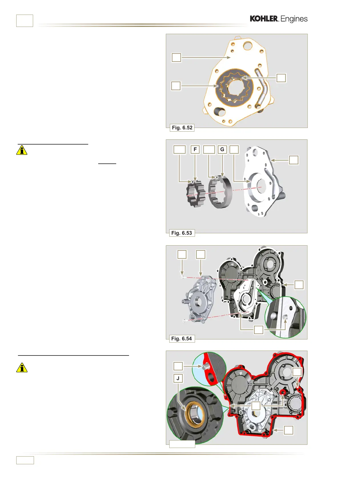
2 - Remove the rotors F and G from the oil pump crankcase E.
6.7.5 Oil pump assembly
Important
• Carry out the checks described in Par. 8.7 prior to assembly.
1 - Check that all surfaces in contact between F, G, H, E and
C are free from impurities - scratches - dents.
2 - When assembling, do not use any type of gasket between
E and C.
3 - Thoroughly lubricate the seat of the rotors H on the oil
pump crankcase E and the two rotors F and G.
4 - Within housing H insert the 2 rotors (in sequence) G and
F, observing the references BP as described in figure (or
refer to Par. 2.10.2).
5 - Check that the 2 pins L are inserted properly in the timing
system crankcase C.
6 - Position the oil pump carter E using the reference pins L.
7 - Clamp the oil pump carter E with the screws D
(tightening torque 10 Nm - ST_06).
6.7.6 Timing system crankcase assembly
Important
• Always replace the oil seal J at each assembly.
• Always replace the gasket P at each assembly.
1 -
Lubricate the lip of the oil seal J.
2 -
Apply a coating of Loctite 5188 around 1mm thick on the
surfaces K of the crankcase C.
3 -
Make sure that the key M (Fig. 6.56) is inserted properly on
the crankshaft and that it is facing upwards.
4 -
Check that the 2 pins N are inserted properly in the timing
system crankcase C.

 Loading...


