6
85
_07
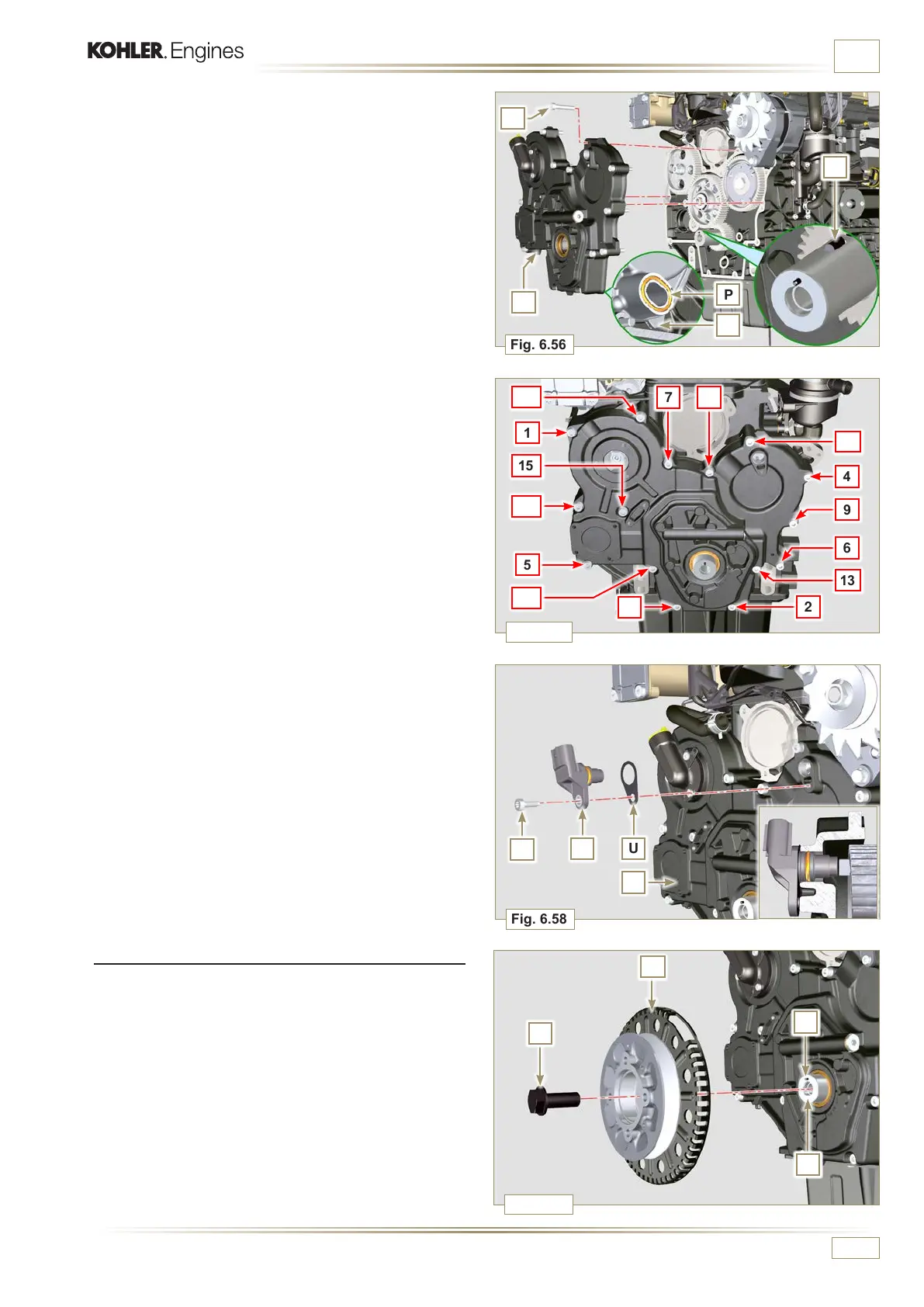
Fig. 6.58
S U
T
Fig. 6.56
P
Q
C
R
M
Fig. 6.59
Y
W
Z
C
1
15
10
5
14
3
12
7 8
2
13
6
9
4
11
Fig. 6.57
A
ED0053029590
INFORMATION FOR REPLACING THE FUNCTIONAL UNITS
9 - Assemble sensor S by means of capscrew T on carter C
inserting gasket U (tightening torque at 10 Nm - ST_06).
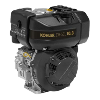
5 - Lubricate and insert the gasket P in the seat of the oil pump Q.
6 - Tighten the tool ST_10 on the crankshaft.
7 - Position the crankcase C on the base, using the reference
pins N, inserting the oil pump Q on the crankshaft.
6.7.7 Crankshaft and phonic wheel pulley assembly
1 - Leave the tool ST_34 mounted (Fig. 6.44).
2 - Check that the pin A is mounted properly on the crankshaft Z.
3 - Position the pulley unit W on the crankshaft Z respecting
the reference with the pin A.
4 - Apply Molyslip grease on the screw thread Y.
5 - Clamp the pulley unit W with the screw Y (tightening torque
at 360 Nm).
6 -
Remove the special tool ST_34 (Fig. 6.44).
8 -
Fit the timing system crankcase C with the screws R
observing the indicated clamping sequence (tightening
torque at 25 Nm).

 Loading...