6
86
_07
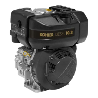
Fig. 6.60
Z
AA
AB
AD
AC
W
C B
A
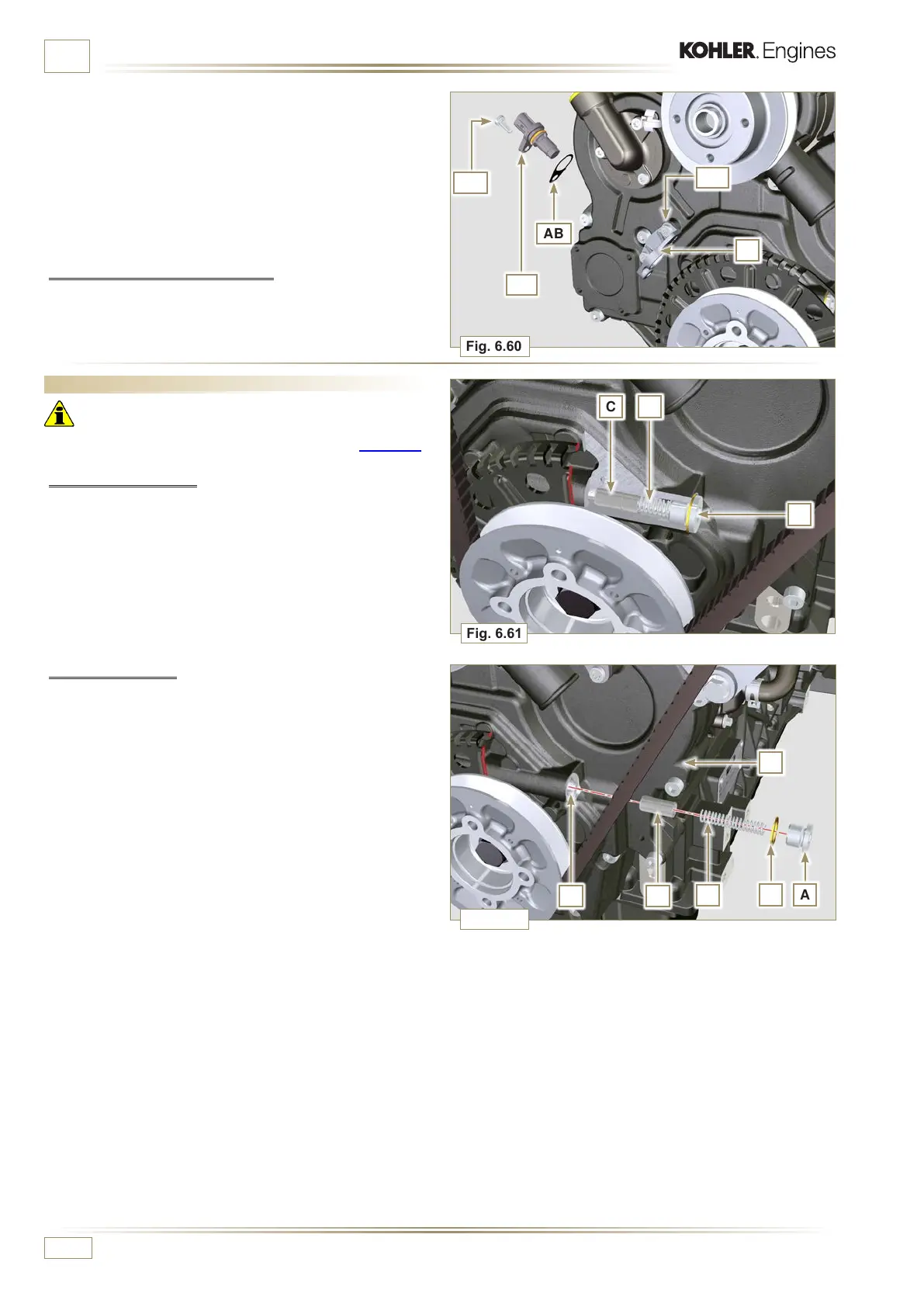
Fig. 6.61
CE
B
AF
D
Fig. 6.62
ED0053029590
INFORMATION FOR REPLACING THE FUNCTIONAL UNITS
7 - Mount the bracket Z with the screws AA (tightening torque
at 10 Nm).
8 -
Perform the operations described in Par. 9.12.
9 -
Insert the shim AB on the sensor AC.
10 -
Clamp the sensor AC on the bracket Z with the screw AD
(tightening torque at 10 Nm).
6.7.8 Coolant pump assembly
11 - Perform the operations described in Par 6.5.2.
6.8 Oil pressure valve replacement
Important
• Before proceeding with operation, carefully read Par. 3.3.2.
6.8.1 Disassembly
1 - Undo cap A.
2 - Remove spring B, check its condition and replace it if
broken.
3 - Remove the valve piston C using a magnet.
6.8.2 Assembly
1 - Lubricate the piston C and fully insert it in the seat E.
2 - Insert the spring B in the piston.
NOTE: Always replace the gasket F after each assembly.
3 - Mount the gasket F on cap A.
4 - Clamp the cap A on the crankcase D (tightening torque at
50 Nm).

 Loading...