6
87
_07
C
F
D
G
AA
Fig. 6.63
J
G
AG
H
K
S
Fig. 6.64
F
E
B
Fig. 6.65
H
B
M
J
N
L
K
E
C
AG
G
H
P
D
F
Fig. 6.66
P
AG
S
K
AA
ED0053029590
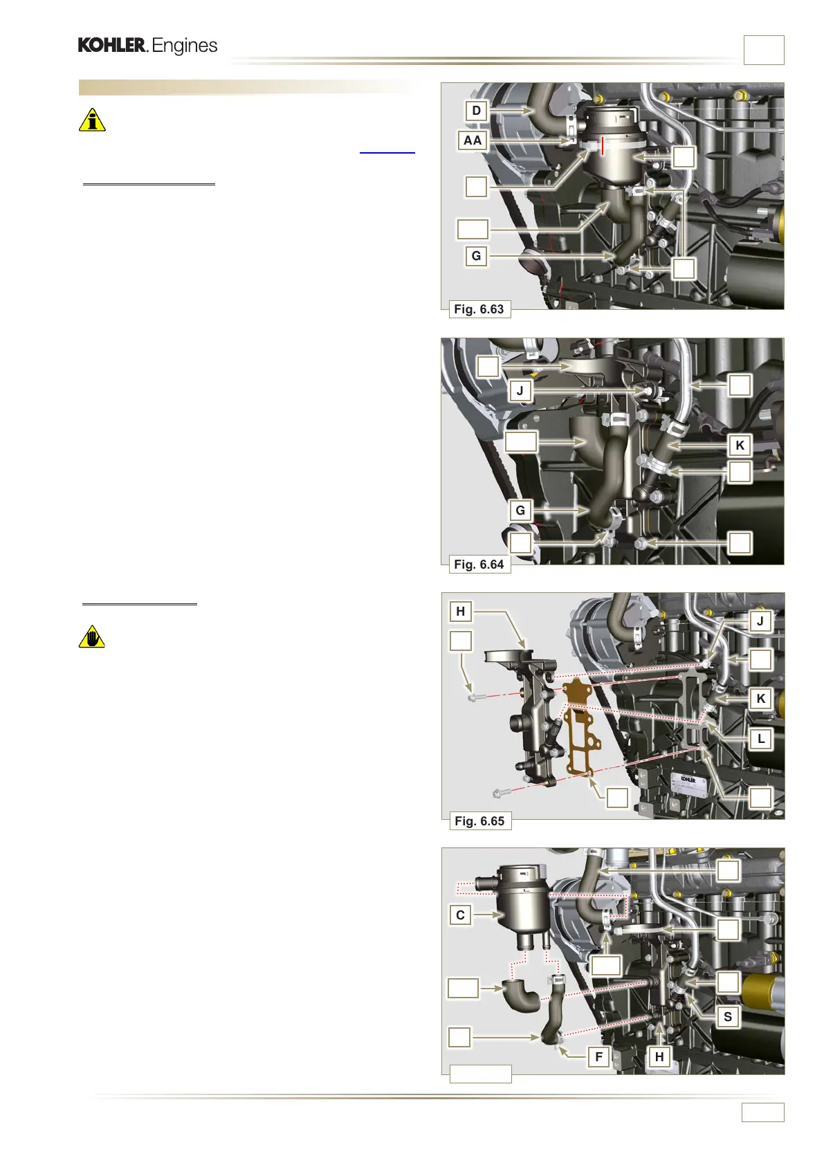
INFORMATION FOR REPLACING THE FUNCTIONAL UNITS
6.9 Oil vapour separator replacement
Important
• Before proceeding with operation, carefully read Par. 3.3.2.
6.9.1 Disassembly
1 - Release the clamp AA and remove the pipe D.
2 - Release the clamps F.
3 - Remove the clamp P cutting it in the point indicated and
remove the separator body C removing it from the hose
AG and G.
4
- Release the clamp F.
5 - Remove the pipes G and AG.
6 - Remove the clamp J.
7 - Undo the screws B.
8 - Release the clamp S from the sleeve K.
9 - Pull the flange H out of the manifold K and remove the
relevant gasket, being careful not to bend the pipe E.
6.9.2 Assembly
Warning
• Always carefully inspect the condition of the tubes, and
replace them if there is any doubt regarding their integrity.
• Always replace the gasket M after each assembly.
1 - Check that the contact surface L is free from impurities.
2 - Position flange H inserting hose K onto the flange union H,
being careful not to bend tube E
3 - Insert the gasket M between the flange H and the
crankcase N.
4 -
Secure the flange H using the screws B on the crankcase
N (tightening torque at 10 Nm).
5 -
Secure the clamp S on the manifold K.
6 -
Fit the pipes G and AG on the flange H.
7 -
Fit the breather body C on the pipes G and D and fit the
pipe G with the clamps F and the pipe D with the clamp
AA.
8 -
Fit the breather body C on the support flange H with the
new clamp P.

 Loading...


