6
89
_07
Fig. 6.72
T
G
F1
G1
F Q SE UC
D
Q
Fig. 6.73
E
H
A
A
B
B
Fig. 6.71
P
L
N
L1
M
H
M1
N1
ED0053029590
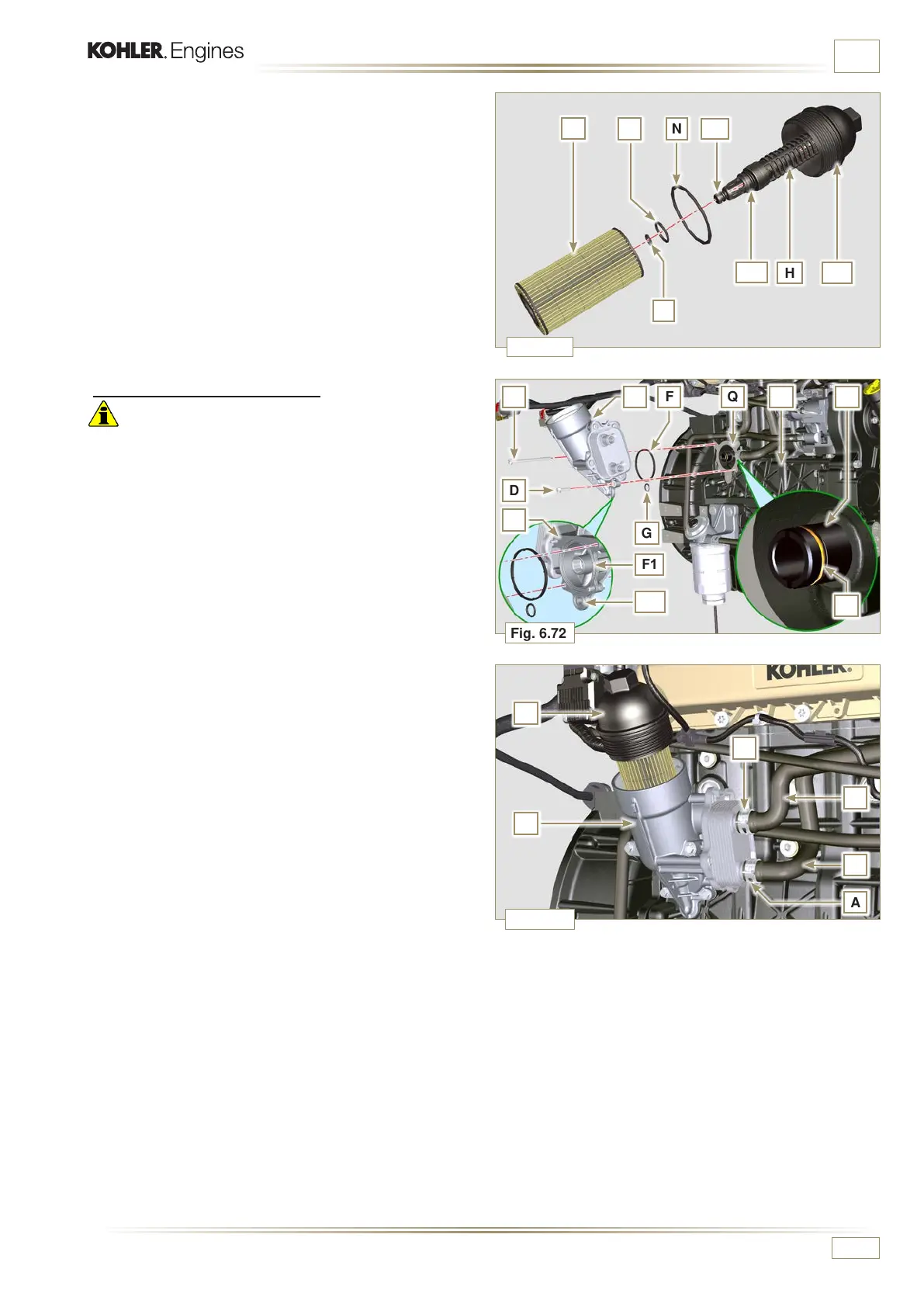
INFORMATION FOR REPLACING THE FUNCTIONAL UNITS
5 - Lubricate and insert gaskets L, M and N in the L1, M1 and
N1 seats of element holder cover H.
6 -
Insert element P into element holder cover H.
6.10.2 Oil Cooler unit assembly
Important
• In the event of assembly of union U on crankcase S, manual
tightening torque with Loctite 2701 on the thread).
1 - Check that the surface Q on the support E and on the
crankcase S are free from impurities.
2 - Lubricate and insert the gasket T on the fitting U.
3 - Lubricate and insert the gaskets on the support E:
F in seat F1;
G in seat G1.
4 - Fit the support R with the screws C and D (tightening torque
at 10 Nm).
5 -
Insert and tighten the cartridge support H on the filter
support E (tightening torque at 25 Nm).
6 - Fit the pipes B on the support E and secure the pipes B
with the clamps A.

 Loading...


