7
95
_07
Fig. 7.13
AD
Fig. 7.15
AG
AF
AL
AH
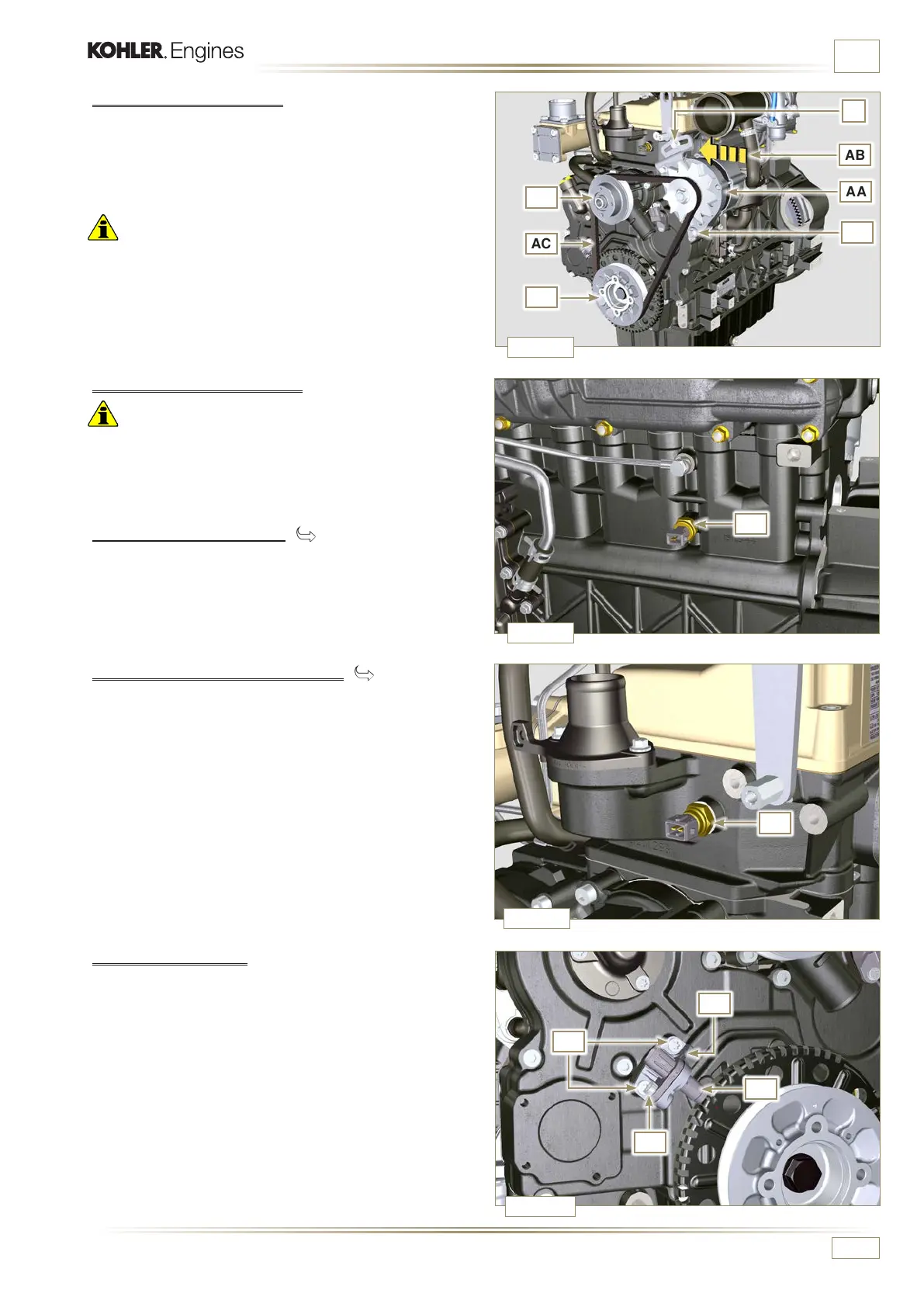
Fig. 7.12
AA
AC
AR
AR
W
AB
Z
Fig. 7.14
AE
ED0053029590
INFORMATION FOR DISASSEMBLY
7.3.3 Belt and alternator
1 - Loosen the screws Z and W.
2 -
Push the alternator AA in the direction of the arrow AB.
3 - Remove the belt AC from the pulleys AR.
Important
• The belt must always be replaced every time it is
disassembled, even if it has not reached the scheduled hours
for replacement.
4 - Undo the screws Z and W and remove the alternator AA.
7.3.4 Sensors and switches
Important
• After disassembly, protect the sensors suitably against
knocks, dampness and any high temperature sources.
• The sensors and switches cannot be repaired, therefore they
must be replaced in the event of anomalies.
7.3.4.1 Oil pressure switch ( )
1 - Unscrew and remove the oil pressure switch AD.
7.3.4.3 Speed sensor
1 - Undo the screw AF and remove the sensor AG with the
relative spacer (ST_06).
2 - Undo the screws AH and remove the sensor (ST_06).
7.3.4.2 Coolant temperature sensor ( )
1 - Unscrew and remove the coolant temperature sensor AE.

 Loading...


