EasyManua.ls Logo

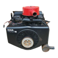
Kohler MAGNUM M18

Kohler MAGNUM M18
139 pages
To Next Page IconTo Next Page
To Previous Page IconTo Previous Page
Loading...
M18
&
M20
SECTION
11
REASSEMBLY
The
following
sequence
is
suggested
for
complete
engine
reassembly.
This
procedure
assumes
that
all
components
are
new
or
have
been
reconditioned,
and
all
component
subassembly
work
has
been
com-
pleted.
This
procedure
may
have
to
be
varied
slightly
to
accommodate
options
or
special
equipment,
Make
sure
old
RTV
sealant
has
been
removed
from
compo-
nents
using
this
before
reassembling.
NOTE:
Make
sure
the
engine
is
assembled
using
all
specified
torque
values,
tightening
se-
quences,
and
clearances.
Failure
to
observe
specifications
could
cause
severe
engine
wear
or
damage.
NOTE:
Always
use
new
gaskets.
NOTE:
Make
sure
all
components
have
been
cleaned
BEFORE
reassembly.
TYPICAL
REASSEMBLY
SEQUENCE
.
Install
oil
pump
and
oil
pickup.
.
Install
cross
shaft
and
governor
gear.
.
Install
connecting
rods.
.
Install
bearings
and
crankshaft.
.
Install
tappets
and
camshaft.
.
install
camshaft
bore
plug
and
seal
crankcase.
.
Install
front
oil
seal.
.
Install
oil
filter
adapter.
.
Install
oil
pressure
relief
valve,
closure
plate,
and
rear
oil
seal.
10.
Install
piston
rings.
11.
Install
pistons
in
cylinder
barrels.
12.
Install
cylinder
barrels.
13.
Measure
valve-to-tappet
clearance.
14.
Install
valves.
15.
Install
cylinder
heads
and
spark
plugs.
16.
Install
stator.
17.
Install
electric
starter,
18.
Install
fan,
flywheel,
and
grass
screen.
19.
Install
bracket
and
ignition
module.
SCONAHAYON=A
20.
Install
fuel
pump.
21.
Install
valve
cover
and
breather.
22.
Install
blower
housing,
cylinder
head
baffles,
and
top
baffle.
23.
Install
solenoid,
key
switch,
rectifier-regulator,
and
connect
wiring.
24.
Install
carburetor
and
intake
manifold.
25.
Install
air
cleaner.
26.
Install
exhaust
elbows
and
mufflers.
27.
install
oil
filter.
INSTALL
O!L
PUMP
AND
OIL
PICKUP
Oil
Pump
1.
Install
the
shim
spacer
(next
to
support
rib),
oil.
pump
drive
gear
(slotted
end
of
gear
hub
towards
spacer
and
rib),
and
oil
pump
drive
shaft
(through
support
rib
and
into
pump
cavity).
Refer
to
Figures
11-1
and
11-2.
Roll
Pin
d
|
Q
Ш
Gear
Spacer
Figure
11-1.
Installing
Oil
Pump
Drive
Gear.
2.
Rotate
the
drive shaft
and
drive
gear
until
hole
in
shaft
is
aligned
with
slot
in
gear
hub.
3.
Lubricate
a
new
roil
pin
with
grease.
Drive
the
roll
pin
until
it
is
flush
with
gear
hub.
Refer
to
Figure
11-2.

Related product manuals