TP-7092 8/1818 Section 1 Descriptions and Service Views
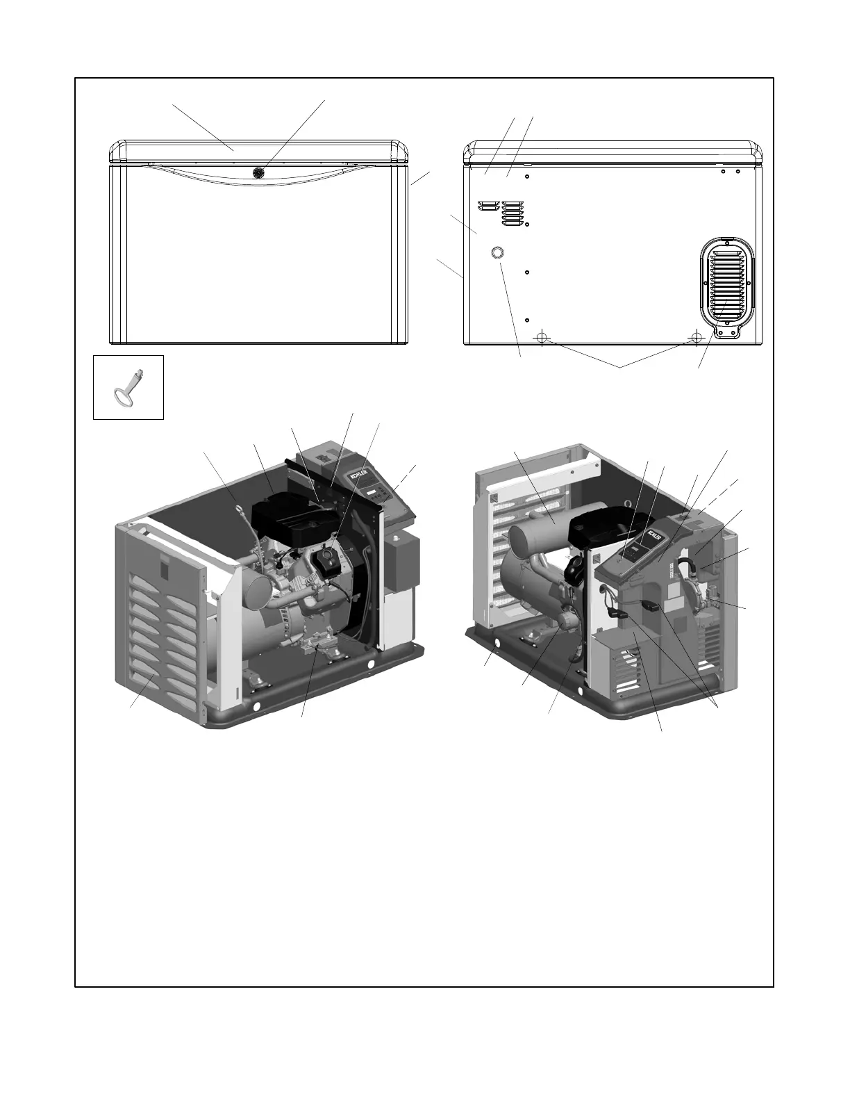
1.8 Service Views
16
1
3
19
12
24
27
ADV8928
22
13
29
1. Hinged roof
2. Lock
3. Air intake
4. Enclosure key, provided with generator set
5. High voltage electrical in
6. Optional emergency stop button location
7. Lifting holes
8. Fuel inlet
9. Air intake
10. Low voltage electrical in
11. Oil check (dipstick)
12. Air cleaner
13. Oil filter (20 kW models)
14. Auxiliary winding circuit breaker
15. Oil fill
16. AC receptacles for accessories (not shown)
17. Oil drain valve
18. Exhaust outlet
19. Muffler
20. USB connector (for firmware updates)
21. RDC2 controller
22. Line circuit breaker
23. Nameplate location
24. Field-connection terminal block (behind panel)
25. Digital spark advance ignition (DSAI) lead location (14RCA/L
only)
26. Thermostat location
27. Fuel system
28. Battery cables (provided)
29. Engine starting battery location (battery purchased separately)
30. Oil drain hose (shown in storage position)
31. Oil filter (14 kW models)
30
21
20
23
ENCLOSURE PANELS
REMOVED TO SHOW DETAIL
9
11
15
2
4
25
8
6
5
10
26
7
17
3
7
18
28
14
31
Figure 1-2 Service Views (20 kW model shown)
 Loading...