TP-6807 12/11 19Section 2 Installation
2.5.6 Interface Module Connection
The interface module must be connected to a Kohlerr
generator set equipped with the RDC2 or DC2
controller. The generator set is typically equipped with a
field-connection terminal block. See the generator set
Installation Manual for the location of the terminal block.
Note: This document gives connection information for
one Model RXT transfer switch connected to a
generator set equipped with an RDC2 or DC2
controller. If additional accessory modules such
as a programmable interface module (PIM) or a
load control module (LCM) are connected, refer
to the generator set installation manual for cable
requirements and connection instructions.
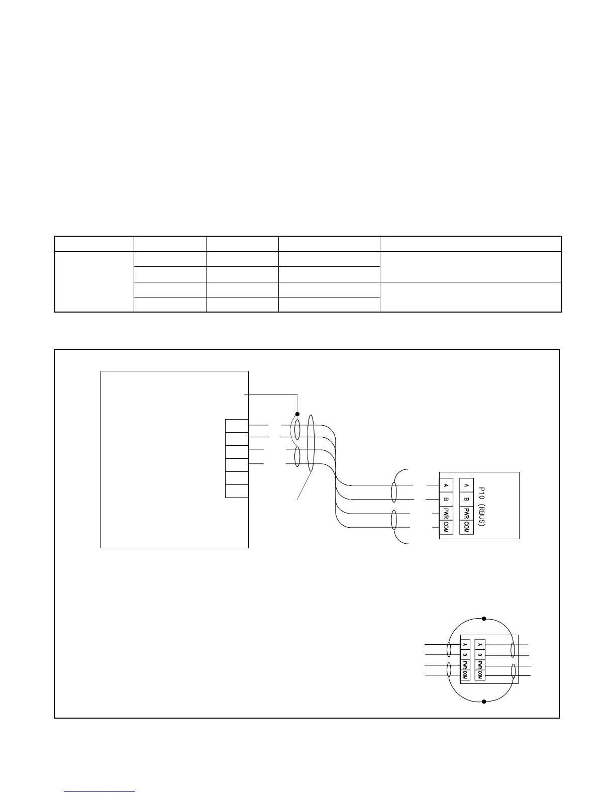
See Figure 2-9 and Figure 2-10. Use 20 AWG Belden
#9402, 8723, or equivalent shielded, twisted-pair cable
to connect P10-1 through P10-4 on the controller
interface module to the generator set terminal block
connections A, B, PWR, and COM. The maximum cable
length is 61 meters (200 ft.).
Alternatively, 12--14 AWG wire can be used for the PWR
and COM connections only. If 12--14 AWG wire is used
for the PWR and COM connections, the maximum cable
length is 152 m (500 ft.) if one Model RXT transfer
switch and no accessory modules are connected to the
generator set.
Note: Connections 3 and 4 on the generator set are not
used with the Model RXT transfer switch.
Terminal Block Connection Designation Description Wire Size
P10
P10-1 A Communication Line
20 AWG shielded twisted-pair,
Belden 9402, 8723, or equivalent
P10-2 B Communication Line
P10-3 PWR 12 VDC
20 AWG shielded twisted-pair Belden 9402
or 12--14 AWG wire
P10-4 COM 12 VDC
Figure 2-9 Controller Interface Connections
1. Communication cable Belden #9402 or equivalent 20 AWG shielded, twisted-pair cable
Interface Board on the Model
RXT Transfer Switch
Note: Generator set terminal block connections 3 and 4 are
NOT USED with the Model RXT ATS.
RXT
Leave one end of each cable shield disconnected.
If accessory modules are connected in series, connect
the cable shields as shown below and refer to the
generator set installation manual.
Generator Set
COM
PWR
B
A
Connect one end of each cable shield to
GROUND at the generator set.
RXT
COM
PWR
B
A
1
GND
Generator Set Terminal Block TB1.
See the generator set manuals for location.
Check the decal on the generator set for terminal
block connections.
A
B
COM
PWR
3
4
TB1
Figure 2-10 Interface Module Connection to Generator Set Field-Connection Terminal Block