EasyManua.ls Logo

Kohler KCP MPAC 1000 - User Manual

Kohler KCP MPAC 1000
76 pages
To Next Page IconTo Next Page
Loading...
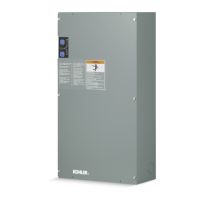
Automatic Transfer Switches
Operation and
Installation
Models:
KCT, KCP
Power Switching Device:
Standard
Open-Transition 30 to 4000 Amps
Programmed-Transition 150 to 4000 Amps
Electrical Controls:
MPAC 1000t
TP-6126 8/02b

Table of Contents

Questions and Answers:

Kohler KCP MPAC 1000 Specifications

General IconGeneral
BrandKohler
ModelKCP MPAC 1000
CategorySwitch
LanguageEnglish

Summary

Product Identification Information

Safety Precautions and Instructions

Accidental Starting Warnings

Warnings regarding accidental starting of electromechanical equipment, causing severe injury or death.

Battery Safety Warnings

Warnings regarding sulfuric acid and explosion hazards associated with batteries.

Hazardous Voltage and Electrical Shock

Dangers of hazardous voltage and electrical shock during operation and servicing.

Heavy Equipment Safety

Warning about unbalanced weight and proper lifting procedures for heavy equipment.

Moving Parts and Airborne Particles Safety

Safety precautions related to moving parts and airborne particles during operation.

Section 2 Installation

Electrical Wiring Guidelines

Guidance on wiring connections, including sources, loads, and control circuits.

AC Power Connections

Details on determining cable size and making AC power connections to the transfer switch.

Section 3 Setup and Test

Controller Main Logic Board

Overview of the main logic board, including DIP switches and connectors.

System Parameters and Time Delays

Details factory settings for system parameters and lists adjustable time delays.

Generator Set Prep and Functional Test Overview

Steps for generator set prep and introduction to functional tests like manual, voltage, auto.

Manual Operation Test and Voltage Check

Procedures for manual operation checks and verifying source voltage/phase compatibility.

Automatic Operation Test

Procedure to simulate source failure and verify automatic transfer to standby operation.

Section 4 Operation

Automatic Operation Sequences

Explains automatic transfer sequences for open and programmed-transition switches.

System Test Procedures

Details tests for simulating source failure and verifying transfer sequences.

Peak Shave;Area Protection Sequence

Explains the operation sequence when peak shave or area protection input is received.

Faults Overview

Describes common faults and how the Service Required LED indicates them.

Section 5 Scheduled Maintenance

Service Schedule

Provides a detailed service schedule with recommended intervals for various maintenance tasks.

Related product manuals