TP-6126 8/02 49Section 6 Accessories
modules are connected and the address DIP switches
are set correctly. Check the diagnostic LED to verify that
the module is receiving power and communicating with
the controller.
I/O Module Not Installed. If the software detects an I/O
module that is connected but not expected by the setup
program, the Service Required LED flashes and the
software logs the message, “I/O Module Not Installed.”
The system ignores the board if it does not find the setup
definition. Check that the number of I/O modules
expected in the Setup Program matches the number of
modules installed on the transfer switch. Check that the
I/O module address DIP switches are set correctly.
Check the diagnostic LED.
I/O Module Communications Lost. If communication
to an I/O module that was previously installed and
working is lost, the Service Required LED flashes and
the software logs the message “I/O Module
Communications Lost.” Check the I/O module
connections and diagnostic LED.
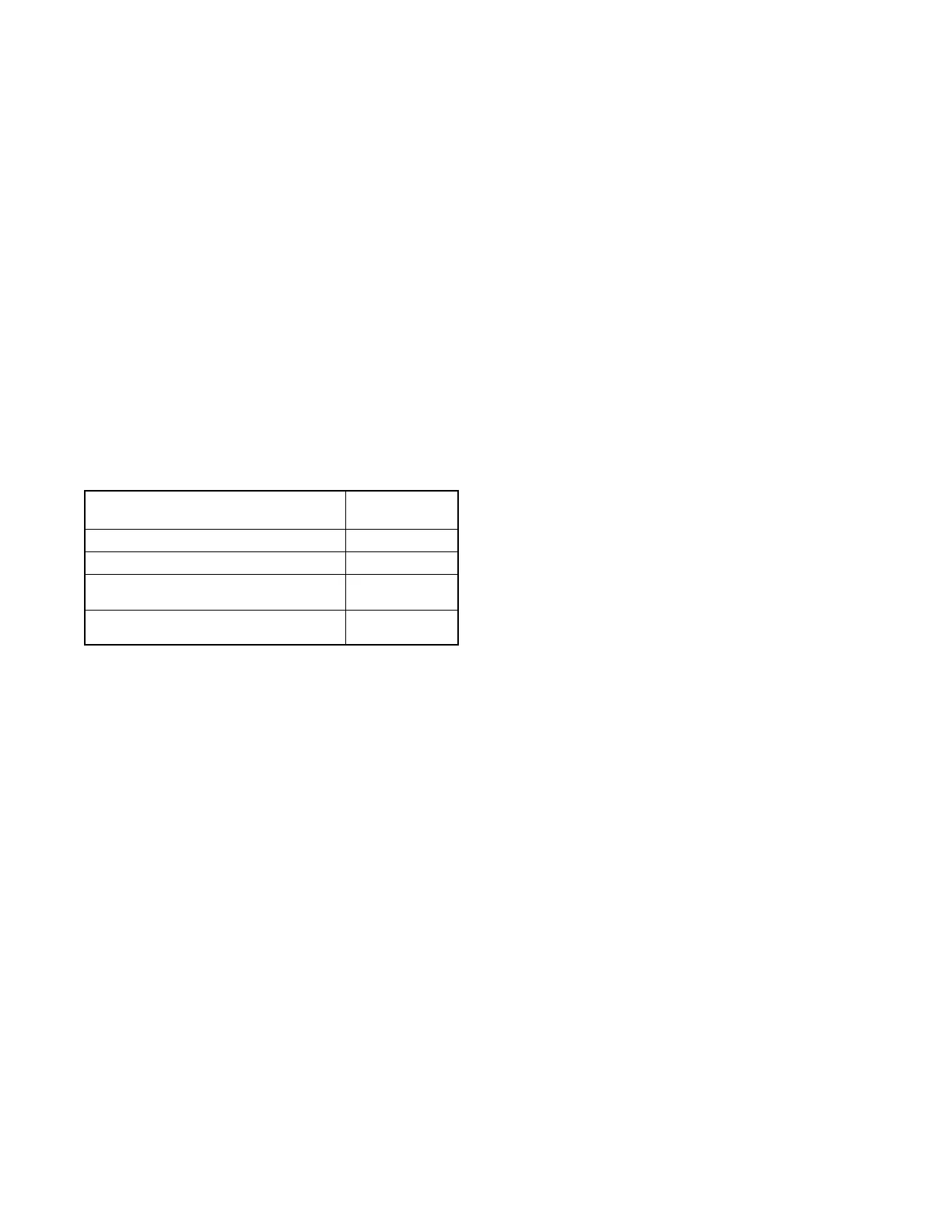
I/O board
Status
Diagnostic
LED
Unpowered Off
Operating correctly On, Steady
Power but no communication with
control board
Quick Flash
(2 Hz)
No defined program at I/O module
address
Slow Flash
(0.5 Hz)
Figure 6 -18 I/O Module Diagnostic LED
6.6 Load Shed (Forced Transfer to
OFF)
6.6.1 Description
The load shed (forced transfer to off) accessory allows
the removal of non-critical loads from the Source E
generator set. The accessory requires an external
signal (contact closure) to initiate transfer to the Off
position. The load shed (forced transfer to off)
accessory is available only for programmed-transition
transfer switches.
When the forced transfer to off input is activated (contact
closed), the contactor moves from Source E to the OFF
position immediately, ignoring all time delays. If the
normal source is available when the input is activated,
the ATS transfers to the Off position and then to Source
N, executing all programmed time delays. If Source N is
not available, the ATS remains in the Off position until
the input is deactivated. When the input is deactivated,
the ATS transfers back to Source N, if available,
executing all programmed time delays. If Source N is
not available, the ATS transfers to Source E.
The load shed (forced transfer to off) function only sheds
loads connected to Source E. The preferred source
selector switch position (if equipped) does not affect this
function.
6.6.2 Connection
On transfer switches with the factory-installed load shed
accessory, the forced transfer to off input is assigned to
main logic board terminal strip programmable input #2
(terminals 8 and 9). Connect the forced transfer to off
signal from the generator set controller or other
customer device to terminals 8 and 9 following the
instructions in Section 3.3.2. Use #12--24 AWG wire
and tighten the terminals to 0.5 Nm (4.4 in. lb.).
6.7 Security Cover
The gasketed, hinged security cover prevents
unauthorized access to the transfer switch controls and
protects the user interface from harsh environmental
conditions. Use a customer-supplied padlock to lock the
cover.
The cover is available with or without a window for
NEMA 1 enclosures. NEMA 3R enclosures include a
windowless cover as standard equipment.
 Loading...


