TP-6126 8/0248 Section 6 Accessories
gm21115a
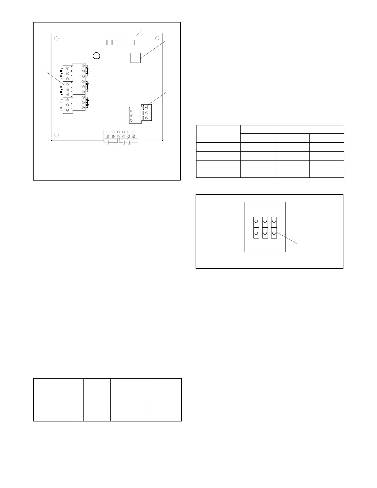
1. Controller harness connection
2. Address DIP switches
3. Input connections
4. Output connections
3
4
TB2
1
6
P2
-- -- O P E N -- --
321
DIAGNOSTIC
SW1
IN1+
IN1--
DIGITAL
IN2+
IN2--
RDO1 RDO2 RDO3
RDO5 RDO6
RDO4
RELAY OUTPUT
INPUT
LED1
6
P1
TB1
1
2
Figure 6 -14 I/O Module Input and Output
Connections
I/O Module Connection Procedure
1. Disconnect power to the transfer switch before
connecting to the I/O modules.
2. Remove the I/O module cover and connect devices
to the I/O module input terminals on terminal block
TB1 or output terminals on terminal block TB2. See
Figure 6-14 for the terminla block locations. The
output connections on the I/O module are labelled
RDO (relay driver output) 1 through 6. Use wire
sizes within the specifications in Figure 6-15 for the
input and output connections.
3. Tighten the connections to 0.5 Nm (4.4 in. lb.).
4. Record the connections on the label on the cover
and replace the cover.
5. Use the Setup Program to set up the I/O board
communications and to define the I/O board inputs
and outputs. Refer to the Setup Program
Operation Manual for instructions.
Component
Number
of Wires
Wire Size
Range
Tightening
Torque
Controller terminal
strip I/O terminals
1 #12--24 AWG
0.5 Nm
I/O board terminals 1 #14--26 AWG
4.4 in. lb.)
Figure 6 -15 Input and Output Connection
Specifications
6.5.3 I/O Module Address
Each I/O Module requires a unique address.
Factory-installed I/O module addresses are set at the
factory.
To check the I/O module addresses, compare the DIP
switch settings with Figure 6-16, starting with the
module connected to the controller harness.
Figure 6-14 shows the address DIP switch location on
the I/O module. Push down the end of the DIP switch
near the OPEN label to open the switch, or push down
the other end to close it. See Figure 6-17.
Address DIP Switches
Number
1 2 3
1 Closed Closed Closed
2 Closed Closed Open
3 Closed Open Closed
4 Closed Open Open
Figure 6 -16 I/O Module Address DIP Switches
1
6126
1. Push this side down to open.
OPEN
123
Figure 6 -17 I/O Module Address DIP Switches
6.5.4 I/O Module Faults and Diagnostics
When power is applied to the system, the controller
attempts to initiate communication with each connected
I/O board. The following faults may occur on powerup if
the I/O modules are not correctly installed, addressed,
or configured in the setup software. Check the LED on
each I/O module for diagnostic information in the case of
a fault.
Diagnostic LED. Each I/O module has a diagnostic
LED that lights or flashes to indicate the I/O board status
as described in the table in Figure 6-18.
I/O Module Not Found. If the system does not detect
an I/O module at an expected address, the Service
Required LED flashes and the software logs the
message, “I/O Module Not Found”. Check that the
number of I/O modules installed matches the number
expected by the setup program. Check that the I/O
 Loading...


