TP-6126 8/0216 Section 2 Installation
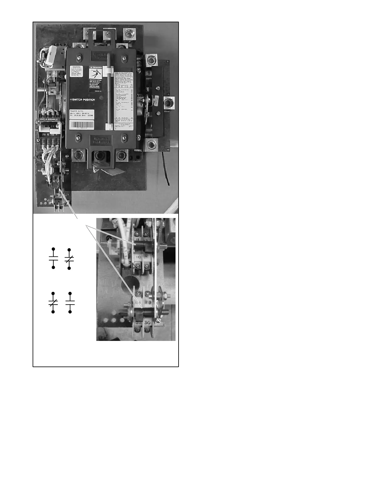
1. Auxiliary contacts 10--13 and 29--32 (contacts shown with
contactor in Normal position)
6126
1
12
1311
10
31
32 30
29
Figure 2 -26 Auxiliary Contacts, 225--400 Amp
Open-Transition Models
2.5.4 Controller Ground
Verify that the grounding wire is connected from the
controller’s lower left mounting stud to the enclosure.
This connection provides proper grounding that does
not rely upon the door hinges.
Note: Do not connect the controller harness to the
contactor until instructed to do so in the voltage
check procedure, Section 3.7.2. Disconnect the
power before connecting or disconnecting the
controller harness.
 Loading...


