TP-6126 8/02 21Section 3 Setup and Test
End Time Delay Input. Assigned to terminals TB1-8
and TB1-9 (programmable input #2). Allows a remote
signal to end an active time delay. The signal ends only
the time delay that is active at the time the signal is
applied. Repeated signals are required to end
additional time delays. Does not end the
programmed-transition time delays or an exerciser run.
Other Inputs and Outputs. Other input and output
functions can be assigned to the programmable TB1
terminals. Refer to Section 6 for lists of available
programmable inputs and outputs. Use the Setup
Program to change the input and output assignments if
necessary.
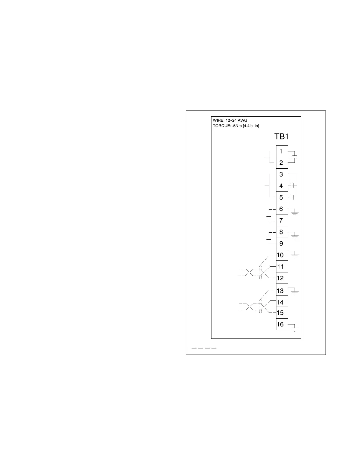
Connections. Connect input and output leads to the
controller terminal strip on the main logic board (MLB).
To gain access to the terminal strip, open the plastic
housing by pushing up on the latch on the bottom of the
cover and swinging the cover up and out. The cover is
hinged at the top. Lift the cover off the hinges to remove
it completely, if necessary. Refer to the label on the
plastic housing or Figure 3-9 for the connections. Use
#12--24 AWG wire and tighten the connections to 0.5
Nm (4.4 in. lbs.).
The controller board terminal strip has two
programmable inputs. Each input has a signal and a
return connection. Connect inputs to terminals 6 and 7
or 8 and 9 on terminal strip TB1. Record the connections
on the label provided. Use the setup program to assign
the input functions if they are different from the default
assignments shown in Figure 3-7.
The main logic board has one programmable output,
which is factory-assigned to the load bank control output
function. Connect to terminals 3 and 4 or 3 and 5 on
terminal strip TB1. Use the setup program to assign the
output function if it is different from the default
assignment.
Note: Always replace the cover before energizing the
transfer switch controls.
3.3.3 Communications Connections
The controller has two communications connections.
Serial Port. For connection to a personal computer to
run the Setup Program software. This is a non-isolated
RS-232 port with a connection speed of 57.6 kbps.
Modbusr
rr
r Network Interface (MNI). For connection to
building management systems, programmable logic
controls, etc. This is a non-isolated RS-485 port with
connection speeds of 9.6 kbps and 19.2 kbps. Use RTU
(remote terminal unit) protocol for communication
through this port.
Connect the Modbus input and output to the terminals
shown in F igure 3-9. Use #12--24 AWG twisted-pair
wire; Belden cable #9841 or equivalent is
recommended. Connect the shield to ground as shown
in Figure 3-9. Tighten the connections to 0.5 Nm
(4.4 in. lbs.).
Note: Contact Kohler Co. for information about
Modbusr communication protocol.
GM22366
MODBUS RS485
A(--)
A(--)
B(+)
B(+)
MODBUS RS485
PROGRAMMABLE
INPUT 1
PROGRAMMABLE
INPUT 2
PROGRAMMABLE
OUTPUT
TRANSFER
PRE-SIGNAL
10A@30VDC/250VAC
2A@30VDC/250VAC
Customer connections
Figure 3 -9 Terminal Strip TB1 Connections
Modbusr is
registered tr
dem
rk o
Schneider Electric.
 Loading...


