TP-6126 8/02 47Section 6 Accessories
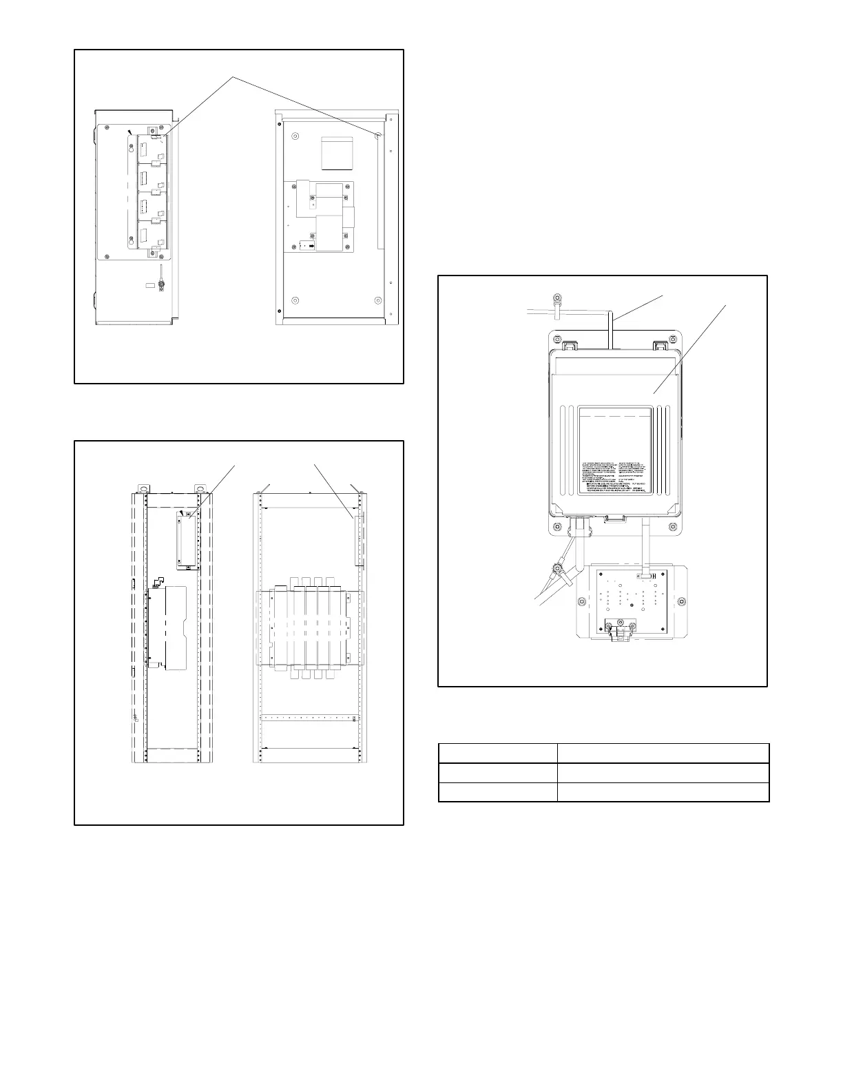
1
GM21360
1. I/O modules
Figure 6 -10 Typical I/O Module Locations (welded
enclosures)
gm21360b
1. I/O module locations (typ.)
Side View
Front View
11
Figure 6 -11 Typical I/O Module Locations (framework
enclosures)
6.5.2 I/O Module Connection
Optional input/output (I/O) modules are connected to
the controller by a factory-installed harness.
Figure 6-12 shows the controller connection.
The input and output ratings are shown in Figure 6-13.
Figure 6-14 shows an I/O module with its input and
output terminal blocks and address DIP switches.
Each I/O Module requires a unique address.
Factory-installed I/O module addresses are set at the
factory.
GM21079-A
1. I/O module harness GM21341
2. Transfer switch controller
1
2
Figure 6 -12 I/O Circuit Board Module Harness
Connection to Transfer Switch Controller
I/O Module Item Rating
Input 16 mA@12 VDC
Output 2 A@250 VA C
Figure 6 -13 I/O Module Ratings
 Loading...


