TP-6126 8/02 17Section 3 Setup and Test
Section 3 Setup and Test
3.1 Introduction
This section explains the setup and test of the transfer
switch. Follow the instructions in this section after
completing the physical installation described in the
previous section.
Note: Be sure to perform the functional tests explained
in Section 3.7 before putting the transfer switch
into operation.
The instructions in this section explain how to set up the
system to operate using factory default settings. This
section includes:
D User interface panel pushbuttons and LED indicators
D DIP switch functions and settings
D Main logic board input and output connections and
default settings
D Communications connections
D Factory default settings for voltage, frequency, and
time delay functions
D Functional tests
D Exerciser setup
D Warranty registration
The transfer switch is designed to be set up and
operated using the factory settings for time delays,
voltage and frequency pickup and dropout, and other
system parameters. To view and change the system
settings, a personal computer running the
MPAC-1000t Setup Program is required. See
TP-6135, Software Operation Manual, for instructions to
use the Setup Program.
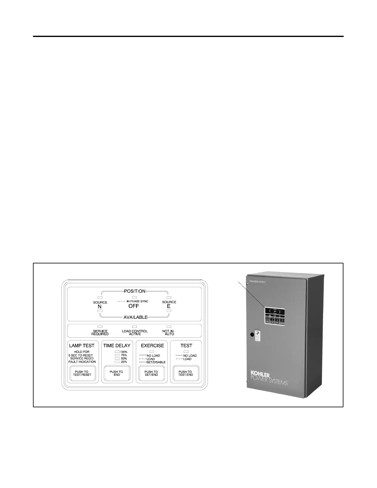
3.2 User Interface Panel
3.2.1 Pushbuttons and LED Indicators
The user interface panel is located on the transfer switch
door. Figure 3-1 shows the user interface pushbuttons
and LED indicators. The LEDs light steadily or flash to
indicate different ATS conditions. The tables in
Figure 3-2 and Figure 3-3 describe the functions of the
pushbuttons and LED indicators. Refer to the
appropriate section for more details about functions
listed in Figure 3-3 and Figure 3-2; see the Table of
Contents.
Figure 3-4 lists the fault conditions that cause the
Service Required LED to light or flash. Steady
illumination indicates that maintenance is needed;
flashing indicates that service is required immediately.
GM211077A
1
1. User interface panel location
Figure 3 -1 User Interface Panel
 Loading...


