TP-5353 8/94 Operation 2-13
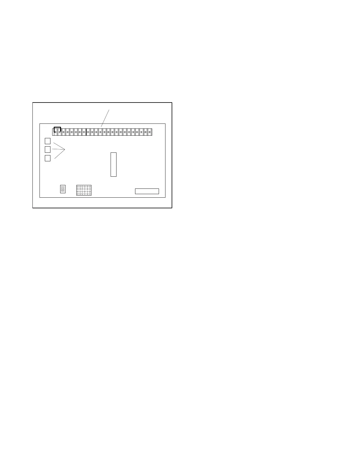
23. Controller TB1 Terminal Strip (on Circuit
Board). Terminal strip allows connection of
generator accessories such as emergency stop
switch, remote start/stop switch, audio/visual
alarms, etc. Crank mode selection (cyclic or
continuous) is also made on the TB1 terminal strip.
Location of the TB1 terminal strip on the controller
circuit board is shown in Figure 2-5. Refer to
appropriate wiring diagrams for additional
information on connecting accessories to the TB1
terminal strip.
P1
P2
G-292806
1
2
1. TB1 Terminal Strip
2. Fuses
Figure 2-5. TB1 Terminal Strip on Controller
Circuit Board
Starting
Local Starting
Move the generator master switch to the RUN position to
start the generator set at the controller.
NOTE
The 6-light controller is equipped with a transient
start/stop function to avoid accidental cranking of the
rotating engine. If the generator master switch is
momentarily placed in the OFF/RESET position then
quickly returned to RUN, the generator set will slow to
249 RPM and recrank before returning to rated speed.
Auto Starting
Move the generator master switch to the AUTO position
to allow start-up by automatic transfer switch or remote
start-stop switch (connected to controller terminals 3
and 4).
NOTE
The 6-light microprocessor controller provides up to 45
seconds of continuous cranking or 75 seconds of cyclic
cranking (crank 15 seconds, rest 15 seconds, crank 15
seconds, etc.) before overcrank shutdown. Cranking
mode (cyclic or continuous) selection is made on the
controller c ircuit board terminal strip. For cyclic
cranking, leave circuit board terminal TB1-9 open.
Continuous cranking is achieved by running a jumper
between circuit board terminal TB1-2 (ground) and
terminal TB1-9.



 To Next Page