5-10 Controller Troubleshooting TP-5353 8/94
Paralleling Engine Gauge Box Controller (Switchgear)
No logic circuitry is supplied with the paralleling engine
gauge box controller. The switchgear provides the logic
to start and stop the generator set. Use the service
literature supplied with the switchgear for
troubleshooting. See the appropriate wiring diagram for
available paralleling engine gauge box controller wiring
diagrams.
The paralleling engine gauge box controller contains a
speed switch which controls crank and overspeed
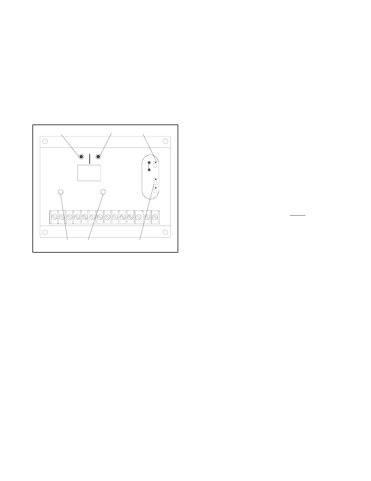
adjustments. See Figure 5-8.
TP-5353-7
CRANK OVERSPEED
OVERSPEED
TEST RESET
OVERSPEED
CRANK
1
2
3
456
E1
E2
1 2 3 5 6 7 8 9 10 11 12 13 144
TACH
CAL
1. Overspeed Test Switch
2. Overspeed Reset Switch
3. Overspeed Adjustment Pot
4. Crank Adjustment Pot
5. Red Overspeed LED
6. Green Crank LED
Figure 5-8. Speed Switch Adjustments
Speed Switch Adjustments
The speed switch is powered by the generator set
battery and the input speed signal is supplied by a
magnetic pickup sensor monitoring the engine camshaft
gear. As the speed of the rotating gear increases, the
frequency of the AC signal from the magnetic pickup
increases until each set point is surpassed. An LED
lights after the speed surpasses the set point and
triggers an internal relay. The set point for the speed
settings are independent and are adjusted precisely
with a 25-turn potentiometer. The crank adjustment
feature latches when the set point has been exceeded.
The overspeed adjustment feature latches and remains
on until power is removed or the overspeed reset button
is pushed. The test button lowers the overspeed setting
by 30% which initiates a shutdown. Periodic testing
during routine engine maintenance is recommended to
ensure positive protection.
Crank Adjustment
Crank adjustment is made by cranking the engine and
simultaneously turning crank adjustment pot slowly
counterclockwise until the desired crank termination
speed is reached. When the cranking termination set
point is reached, the green crank LED illuminates.
The unit is factory set for manual reset. To reinitiate
engine cranking, remove battery power and then
reapply. Automatic reset when the engine speed falls
below the cranking termination set point is done by
removing the 82k-ohm resistor located between
terminals E1 and E2 on the circuit board near the
overspeed pot.
Overspeed Adjustment
Overspeed adjustment is made with the unit running.
Increase the engine speed to 10% below
the desired
overspeed set point. For example: on a 60 Hz unit, the
desired overspeed set point might be 70 Hz and 10%
below this point is 63 Hz. See Section 7—Governors for
specific engine speed adjustment information.
Turn the overspeed adjustment counterclockwise until
the overspeed internal relay energizes and the red
overspeed LED illuminates. Reset the overspeed relay
by pressing the overspeed reset button. After the
engine comes to a complete stop remove battery power
from the speed switch. Reconnect power to the speed
switch and readjust the engine speed to the normal
operating speed using the governor adjustment
procedure. The overspeed set point is tested by
pressing the overspeed test button.
Troubleshooting
Apply DC power and an input speed signal to the speed
switch. Connect a voltmeter to terminal 5 (+) and engine
ground (--). As the speed input frequency is increased
an increase in voltage is noted if functioning correctly. If
the voltage is proportional to frequency, check the wiring
at the terminal strip. If the voltage is not proportional to
frequency, check the output of the magnetic speed
sensor. If the speed sensor is operating and the terminal
strip is wired correctly the speed switch is defective.



 To Next Page