6-12 Generator/Controller Troubleshooting TP-5353 8/94
G-292806
1
2
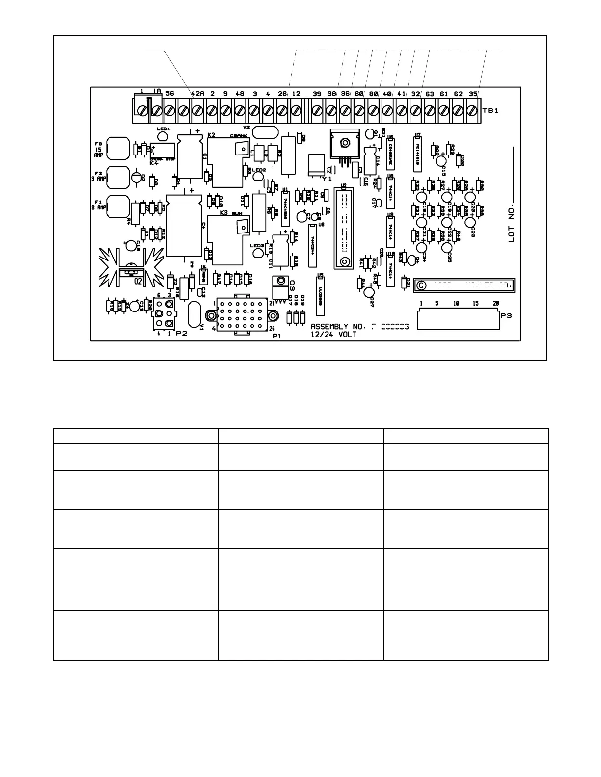
1. TB1-42A 2. TB1—(See chart titled Generator Condition Indicator Terminals)
Figure 6-10. Indicator Lamp Test Connections
Generator Condition Indicator Terminals
Indicator Switch Position/Remarks Check For Voltage Between:
System Ready Master switch in AUTO position; engine
switch in OFF position.
TB1-42A (+) and TB1-60 (--)
High (Engine) Water Temperature
(H.W.T.)
Master switch in RUN position; engine
switch in RUN position; hold toggle
switch to H.W.T for at least 5 seconds
TB1-42A (+) and TB1-36 (--)
Low Oil Pressure (L.O.P.) Master switch in RUN position; engine
switch in RUN position; hold toggle
switch to L.O.P. for at least 5 seconds
TB1-42A (+) and TB1-38 (--)
Auxiliary Fault (16-light controller) or
Low Water Temperature/Auxiliary
(6-light controller)
Master switch in RUN position; engine
switch in RUN position; wait 10
seconds. Flashing AUX lamp indicates
proper operation of all Auxiliary
functions
TB1-42A (+) and TB1-26 (--)
Emergency Stop (local/remote) (if
equipped)
Master switch in RUN position; engine
switch in RUN position; remove switch
lead connected to controller terminals
TB1-1 or 1A.
Not Applicable



 To Next Page