Contents
Contents Page - A -
Kollmorgen 12.99 Series 60WKS
I General
I.1 Preface ......................................................................I-1
I.2 Prescribed usage of the servo amplifiers ............................................I-1
I.3 Abbreviations used in this manual..................................................I-2
I.4 Nameplate ....................................................................I-2
- A.4.028.6/10
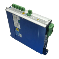
I.5 Equipment description 60WKS ....................................................I-3
I.5.1 Function groups 60WKS ......................................................I-4
I.6 Block diagram .................................................................I-5
- E.4.927.1/5
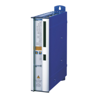
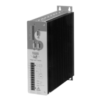
I.7 Frontal view 60WKS ............................................................I-6
- E.4.927.4/18
I.8 Technical Data ................................................................I-7
I.8.1 Technical data for 60WKS-M240/xx-PB...........................................I-7
I.8.2 Permissible ambient conditions, ventilation, mounting position .........................I-8
I.8.3 Cable cross-sections .........................................................I-8
I.8.4 Fuse protection .............................................................I-8
I.9 Interference suppression.........................................................I-9
I.10 Ballast circuit ..................................................................I-9
II Installation and Commissioning
II.1 Important instructions ...........................................................II-1
II.2 Installation ...................................................................II-2
II.2.1 - correct wiring for 60WKS, general diagram ...................................II-4
- E.4.927.1/27
II.2.2 Module backplanes F60WKSMB and R60WKSMB .................................II-5
II.2.2.1 Connector assignments for R60WKSMB ....................................II-5
II.2.2.2 Connector assignments for F60WKSMB ....................................II-6
II.3 Wiring diagrams ...............................................................II-7
II.3.1 Recommended wiring (power) for more than one compact housing ....................II-7
- E.4.927.1/8
II.3.2 Motor connection............................................................II-8
- E.4.927.1/14
II.3.3 Wiring diagram for 60WKS ....................................................II-9
- E.4.927.1/15
II.3.4 Recommended wiring for 2x60WKS with SM56 ... SM100 ..........................II-10
- E.4.927.1/4
II.3.5 Recommended wiring for soft start and brake ....................................II-11
- E.4.916.1/a
II.3.6 Schematic representation of the GND and PE connections ..........................II-12
- A.4.029.1/5
II.4 Commissioning...............................................................II-13
II.4.1 Important notes ............................................................II-13
II.4.2 Notes on commissioning.....................................................II-14
Contents Diagram Page
Contents ...............................................A
Safety instructions ........................................D
Directives and standards ....................................E
- conformance .........................................E
 Loading...