DS4 C
HAPTER
5 - T
ROUBLESHOOTIN
5-3
•
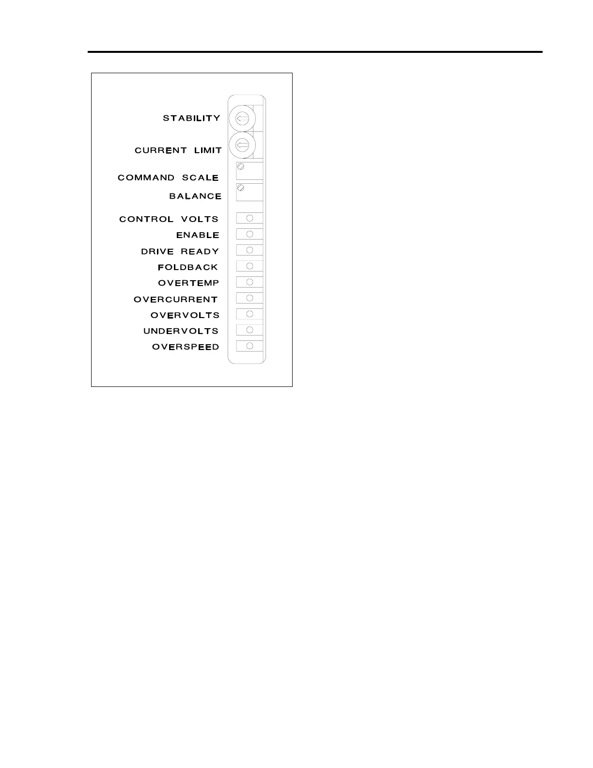
Approximately one second after all power is
applied, the green CONTROL VOLTS LED on
the front of the BDS4 module should become
illuminated to indicate that the Control AC line
input voltage is applied.
•
When the Enable input circuit of the BDS4 is
closed, the green ENABLE LED should
become illuminated indicating that the BDS4 is
now in the enabled mode.
•
No fault (red) LED's should be illuminated.
•
The green DRIVE READY LED may or may
not be illuminated, depending on whether or
not jumper J21 is installed on the BDS4-
COMP Board.
The red FOLDBACK LED will become illuminated
during any situation where the RMS current exceeds
the continuous rating of the BDS4 (peak current is
allowed for only 2.0 seconds). The LED indicates
that the peak current of the BDS4 is automatically
being reduced to the RMS continuous rating. Once
the current demand is reduced, the FOLDBACK
circuit will reset and the LED will turn off. This LED
acts only as an indicator.
If the red OVERTEMP LED becomes illuminated,
the BDS4 will become latched in the Inhibit mode
indicating an overheated BDS4 heatsink.
When the red OVERCURRENT LED becomes
illuminated, it indicates an overcurrent condition
usually due to a shorted load (motor), wiring, or
BDS4 power stage transistor. The BDS4 will become
latched in the Inhibit mode.
If the red OVERVOLTS LED becomes illuminated,
the BDS4 will become latched in the Inhibit mode,
indicating the presence of excessive main DC bus
voltage.
When the red UNDERVOLTS LED becomes
illuminated, the BDS4 will be put into the Inhibit
mode (but not latched) indicating the main DC Bus is
insufficient or absent.
If the red OVERSPEED LED becomes illuminated,
the BDS4 will become latched in the Inhibit mode
indicating that the motor has obtained an excessive
speed, or the resolver cable is miswired or has an
intermittent connection.
The Fault Output contact located within the PSR4/5
power supply module will not be affected by any
faults occurring within the BDS4.
More diagnostic information about the BDS4 is listed
in the Table 5.2.
5.3.4 PSR4/5-12 and 20 Amp Status
LED's
The status of the PSR4/5-12 and 20 amp modules is
indicated by one (1) Green, one (1) Yellow, and two
(2) Red LED's. Refer to Figure 5.2 for the LED
configuration. The diagnostic information indicated
by these LED's is as follows:
•
Approximately 0.25 seconds after the main
power is applied, the green DC BUS LED will
become illuminated to indicate the presence of
voltage on the main DC bus capacitors.
Voltage indication may range in magnitude
from over 300 VDC, during normal operation
with AC line voltage applied, to below 50 VDC
Figure 5.1. BDS4 Status LED's
Artisan Technology Group - Quality Instrumentation ... Guaranteed | (888) 88-SOURCE | www.artisantg.com
 Loading...


