C
HAPTER
5 - T
ROUBLESHOOTING
BDS
5-4
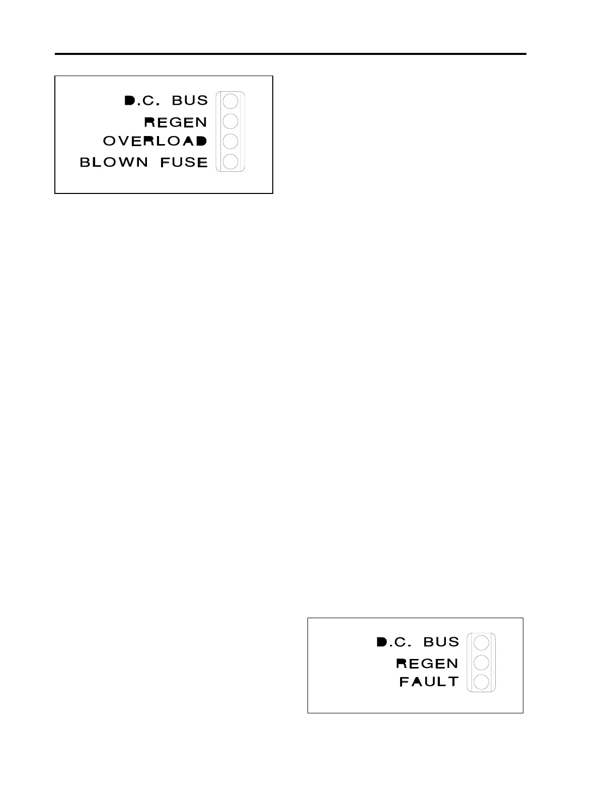
when the line voltage is removed but the bus
capacitors have not completely discharged.
The yellow REGEN LED is for monitoring
purposes only. When this LED becomes
illuminated, the shunt regulator regeneration
circuit is active. No fault is indicated.
The red OVERLOAD LED will become
illuminated in the event the shunt regulator
regeneration circuit experiences an overload
condition. The Fault Output contact will also
open.
The red BLOWN REGEN FUSE LED will
become illuminated and the Fault Output
contact will open in the event the shunt
regulator regeneration fuse blows.
Faults occurring within the PSR4/5 will cause
its Fault Output contact to open.
More diagnostic information about the PSR4/5 12
and 20 Amp LED's is listed in Table 5.3.
5.3.5 PSR4/5-50 and 75 Amp Status
LED's
The status of the PSR4/5-50 and 75 amp models is
indicated by one (1) Green, one (1) Yellow, and one
(1) Red LED. Refer to Figure 5.3 for the LED
configuration. The diagnostic information indicated
by these LED's is as follows:
Approximately 0.5 seconds after the main
power is applied, the green DC BUS LED will
become illuminated to indicate the presence of
voltage on the main DC bus capacitors.
Voltage indication may range in magnitude
from over 300 VDC, during normal operation
with AC line voltage applied, to below 50 VDC
when the line voltage is removed but the bus
capacitors have not completely discharged.
The yellow REGEN LED is for monitoring
purposes only. When this LED becomes
illuminated, the shunt regulator regeneration
circuit is active. No fault is indicated.
The red FAULT LED, when illuminated,
indicates an excessive heatsink temperature
within the unit due to an overload condition
and may also indicate excessive ambient
temperature.
Faults occurring within the PSR4/5 will cause
its Fault Output contact to open.
More diagnostic information about the PSR4/5 50
and 75 Amp LED's is listed in Table 5.4.
5.3.6 BDS4 or PSR4/5 Reset
Procedures
To reset the OVERVOLTS and OVERCURRENT
fault latches within the BDS4 and all fault latches
within the PSR4/5 power supply units, remove all AC
line input voltage for at least five (5) minutes or until
the power stage capacitors are fully discharged. All
other fault latches within the BDS4 amplifiers may be
reset by toggling the RESET input circuit to common
or by removing and reapplying the input voltage as
described previously.
The thermal overload relay with the PSR4/5 50 and
75 amp modules External Regen Resistor(s) is
normally furnished and set for "HAND" reset
operation. In the event of excessive shunt regulator
activity, its auxiliary contact will open. (THIS
CONTACT MUST BE WIRED INTO THE E-STOP
STRING OR AN EQUIVALENT SHUNT DOWN
CIRCUIT.) The thermal overload relay may be reset
by pushing in the reset rod located in the top of the unit.
Figure 5.2. PSR4/5 12,20 Status LED's
Figure 5.3. PSR4/5 50,75 Status LED's
Artisan Technology Group - Quality Instrumentation ... Guaranteed | (888) 88-SOURCE | www.artisantg.com

 Loading...


