PPENDIX
E - O
PTIONS
BDS
E-2
E.2.2 BDS4-OPT2/3A Option Board
The option board can support 10-, 12- 14-, or 16-bit
R/D converters (mounted within the BDS4). The
card may be configured one of three ways:
01- as a differential quadrature encoder interface
with marker pulse.
02- as a 12- to 16-bit buffered parallel resolver
data interface.
03- as a 12- to 16-bit buffered parallel resolver
data interface with drive control signals.
E.2.2.1 BDS4-OPT2/3A-01 BOARD
Electronic Encoder Output
When configured as a BDS4-OPT2/3A-01 board,
only the encoder outputs are offered. The board
functions only to convert the binary (motor shaft)
position information from the R/D (Resolver-to-
Digital) converter, located within the BDS4 amplifier,
to differential quadrature encoder signals with marker
pulse.
The output interface connections are made via
Connector 32, mounted on the BDS4-OPT2/3A-01
Board. This connector is an 8-Pin Molex MINI-FIT
JR connector and is located just to the left of
Connector C1 mounted in the top front of the BDS4
amplifier .
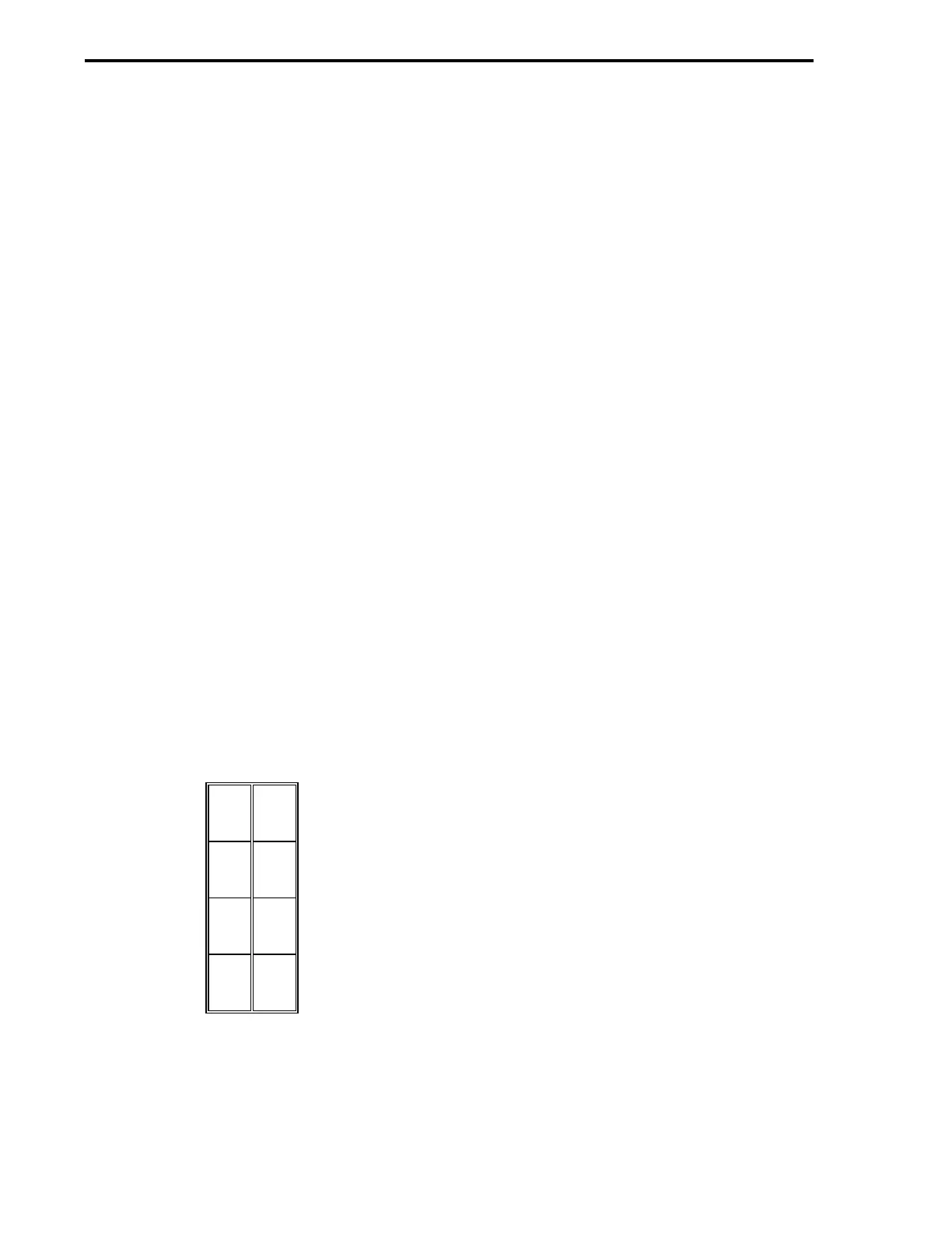
The pin outs are as follows:
OUT A 5 1
______
OUT A
OUT B 6 2
______
OUT B
OUT Z 7 3
______
OUT Z
COM 8 4 COM
Figure E.1. Connector 32
The encoder interface option provides a differential
quadrature synthesized encoder output and a
differential marker pulse output for customer use.
Each output pair (OUT A or A phase, OUT B or B
phase, and OUT Z or Z phase) is driven by a
DS8830/SN75183 differential line driver integrated
circuit. The voltage levels transition between + 5
volts and common. This interface is capable of
sinking and sourcing 40 milliamps of current. The
differential outputs are designed to drive long lengths
of coaxial cable, strip line, or twisted pair
transmission lines with characteristic impedances of
50 to 500 ohms.
The quadrature signal is generated by the following
sequence:
Refer to Drawing D-93179-1.
Up to sixteen parallel resolver data bits are brought to
the BDS4-OPT2/3A Option Board via connectors 7
and 33. These bits first pass through LS244 data
buffers. Next the data bits are routed to a double row
jumper/header (component 35). At this header the
quadrature resolution is selected by manipulating two
jumpers. The resolution can be from 16 to 16384
encoder lines in increments of power of two (2
x
) (i.e.,
16, 32, 64, 128, 256, 512, 1024, 2048, 4096, 8192,
16384). The following jumper table shows the
jumper combinations for the resolutions available.
After two of the twelve data bits have been selected at
the jumper/header block (Component 35) by the two
jumper selections, these two signals are routed to a
pair of Exclusive-Or gates. This is where the
quadrature (A Phase offset from B Phase by 90
degrees) signal pair are generated.
After this the two quadrature signals are latched by a
pair of LS175 flip-flops. The non-inverting output
from each flip-flop drives an LED. The inverting
output from each flip-flop drives a pair of DS8830 or
75183 line drivers. The line driver outputs route
straight across a jumper/header strip (this is used with
other options) and terminate at customer Connector
32.
The marker pulse signal is generated by the following
sequence:
All sixteen parallel resolver data bits are brought to
the BDS4-OPT2/3A Option Board. These bits first
pass through LS244 data buffers. Next the data bits
are routed to a bank of DIP switches consisting of
Components 23 and 26. At these switches the marker
pulse width is selected. For a minimum pulse width
all switches should be closed. As more switches are
Artisan Technology Group - Quality Instrumentation ... Guaranteed | (888) 88-SOURCE | www.artisantg.com
 Loading...


