OM2049 2/13 Safety - Section 20
Page 20-15
MANUAL DC LINK CAPACITOR
DISCHARGE PROCEDURE
Preparation
Follow any and all local and site specific procedures
and requirements for working on off-highway mining
equipment.
Verify that:
• The engine is off and the parking brake is on.
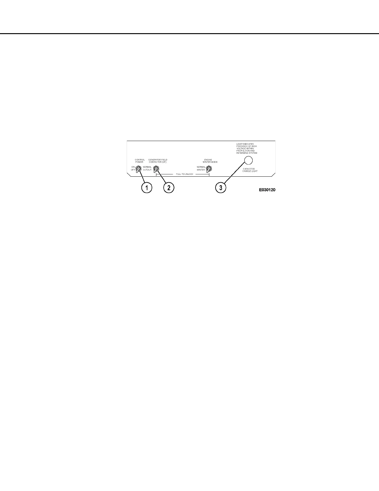
• The generator field is cut out via GF cutout switch
(2, Figure 20-6) in the low voltage area of the
control cabinet.
1. Apply control power for a minimum of 30 sec-
onds. Then, turn off control power using control
power switch (1) on the switch panel.
With control power on, an RP contactor closes
and discharges the DC link through the retard-
ing grids in less than 10 seconds.
FIGURE 20-6. INFORMATION DISPLAY PANEL
1. Control Power Switch
2. GF Cutout Switch
3. Capacitor Charge Light



 To Next Page