SEN02465-01 40 Troubleshooting
16 PC138US, USLC-8
Failure code [DHSFMA] Travel left forward PPC press sensor
abnormality 1
User code Failure code
Trouble
Travel left forward PPC pressure sensor abnormality
(Pump controller system)
E20 DHSFMA
Contents of
trouble
• Signal voltage of travel left forward PPC pressure sensor circuit is below 0.3 V or above 4.5 V.
Action of
controller
• Fixes travel left forward PPC pressure at 0 MPa {0 kg/cm
2
} and continues control.
• If cause of failure disappears, system resets itself.
Problem that
appears on
machine
• Automatic decelerator cannot be reset.
• Travel left forward performance lowers.
Related
information
a If 5V circuit (3) and ground circuit (1) of pressure sensor are connected inversely, pressure sensor
will be broken. Accordingly, take extreme care when checking.
• Travel left forward PPC pressure can be checked with monitoring function.
(Code: 07102 Travel left forward PPC pressure)
• Method of reproducing failure code: Turn starting switch ON or start engine.
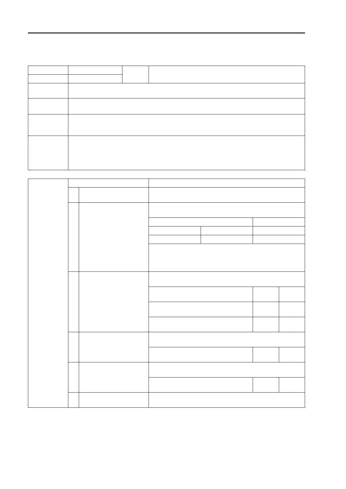
Possible causes
and standard
value in normal
state
Cause Standard value in normal state/Remarks on troubleshooting
1
Defective 5V sensor power
supply 1 system
If failure code [DA25KP] is also displayed, carry out troubleshoot-
ing for it first.
2
Defective travel left forward
PPC pressure sensor (Inter-
nal defect)
a Prepare with starting switch OFF, then turn starting switch ON
or start engine and carry out troubleshooting in each case.
P10 Voltage
Between (3) – (1) Power supply 4.5 – 5.5 V
Between (2) – (1) Signal 0.3 – 4.5 V
If voltage is abnormal, replace travel left forward PPC pressure
sensor with another PPC pressure sensor and check failure code.
(If "E" of failure code goes off at this time, travel left forward PPC
pressure sensor is defective.)
3
Disconnection in wiring har-
ness (Disconnection in wiring
or defective contact in con-
nector)
a Prepare with starting switch OFF, then carry out troubleshoot-
ing without turning starting switch ON.
Wiring harness between C01 (female) (18)
– P10 (female) (1)
Resis-
tance
Max. 1 z
Wiring harness between C01 (female) (69)
– P10 (female) (2)
Resis-
tance
Max. 1 z
Wiring harness between C01 (female) (9) –
J07 – P10 (female) (3)
Resis-
tance
Max. 1 z
4
Ground fault in wiring har-
ness (Short circuit with GND
circuit)
a Prepare with starting switch OFF, then carry out troubleshoot-
ing without turning starting switch ON.
Wiring harness between C01 (female) (69)
– P10 (female) (2)
Resis-
tance
Min. 1 Mz
5
Hot short (Short circuit with
24V circuit) in wiring harness
a Prepare with starting switch OFF, then turn starting switch ON
and carry out troubleshooting.
Wiring harness between C01 (female) (69)
– P10 (female) (2)
Voltage Max. 1 V
6 Defective pump controller
If causes 1 – 5 are not detected, pump controller may be defective.
(Since trouble is in system, troubleshooting cannot be carried out.)

 Loading...