INJECTOR OPERATION
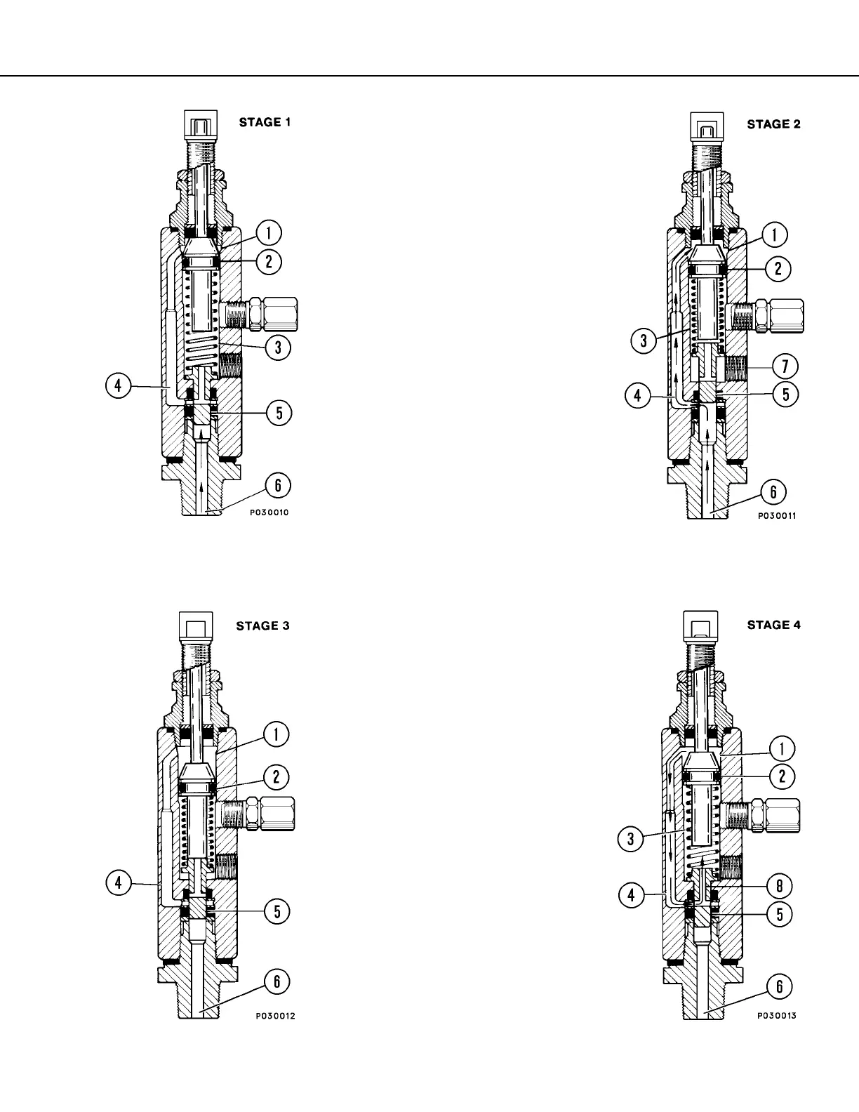
STAGE 1.
Injector piston (2) is in its normal or “rest”
position. Discharge chamber (3) is filled with
lubricant from the previous cycle. With pres-
sure applied from incoming lubricant (6),
slide valve (5) is about to open passage (4)
leading to measuring chamber (1).
STAGE 2.
When slide valve (5) opens to passage (4),
lubricant (6) is admitted to measuring cham-
ber (1). This forces lubricant from discharge
chamber (3) through outlet port (7) to the
lubrication destination.
STAGE 3.
As injector piston (2) completes its stroke, it
pushes slide valve (5) past passage (4). This
stops further admission of lubricant (6) to
passage (4) and measuring chamber (1).
Injector piston (2) and slide valve (5) remain
in this position until lubricant pressure in sup-
ply line (6) is vented.
STAGE 4.
After venting, the injector spring expands,
causing slide valve (5) to move. As the valve
moves, passage (4) and discharge chamber
(3) connect through valve port (8). Further
expansion of the spring causes the piston to
move upward. This forces the grease into
measuring chamber (1) through passage (4)
and valve port (8). Discharge chamber (3)
refills.
The injector is now ready for the next cycle.

 Loading...