Do you have a question about the Komatsu PC58UU-3 and is the answer not in the manual?
Provides a diagram of the machine's overall assembly and key dimensions.
Details technical specifications for the machine, including performance and dimensions.
Lists the weight of various machine components for handling and transport reference.
Highlights critical safety information for machine operation and maintenance.
Outlines general safety guidelines applicable to all operations and maintenance.
Details essential safety preparations before starting any repair or maintenance work.
Explains the internal structure and operational principles of machine components.
Covers procedures for checking, testing, and adjusting machine systems and components.
Provides step-by-step instructions for disassembling and assembling machine parts.
Guides users on how to interpret and utilize the information within the shop manual effectively.
Lists standard torque specifications for nuts and bolts during assembly and maintenance.
Explains the coding system used for colors and symbols in wiring diagrams for clarity.
Provides tables for converting between different measurement units for convenience.
Defines the measurement units used throughout the manual, including SI and gravitational systems.
Details the structure, function, and maintenance standards of the Power Take-Off (PTO) system.
Explains the structure, function, and maintenance standards of the engine cooling system.
Describes the structure, function, and maintenance standards of the machine's power train components.
Covers the structure, function, and maintenance standards related to the swing circle assembly.
Details the structure, function, and maintenance standards of the swing machinery.
Explains the structure, function, and maintenance standards for the track frame and idler cushion.
Describes the structure, function, and maintenance standards of the hydraulic pump.
Outlines the structure, function, and maintenance standards of the machine's control valves.
Explains the Closed Center Load Sensing System's structure, function, and basic principles.
Provides standard and limit values for engine testing and adjustment procedures.
Lists standard and limit values for chassis-related testing and adjustment.
Details test criteria and measurement conditions for electrical system components.
Covers specific procedures for testing and adjusting various machine systems.
Key considerations and steps for effective troubleshooting to prevent recurrence.
Essential guidelines for performing maintenance, especially on electrical and hydraulic systems.
Troubleshooting procedures and error codes specific to the machine's electrical control system.
Identifies common hydraulic and mechanical failures and their causes and remedies.
Guides troubleshooting for issues related to the machine's monitor panel and its functions.
Details crucial safety and procedural precautions for all disassembly and assembly tasks.
Lists specialized tools required for disassembly and assembly procedures, including part numbers.
Provides instructions for the removal and installation of the engine and work equipment pump assembly.
Details the procedures for removing and installing the revolving frame assembly.
Covers the disassembly and assembly procedures for the swing machinery.
Provides disassembly and assembly instructions for the center swivel joint.
Outlines the disassembly and assembly procedures for the idler cushion assembly.
Presents the overall hydraulic circuit diagram for the machine.
Shows the first part of the electrical circuit diagram, illustrating system connections.
| Brand | Komatsu |
|---|---|
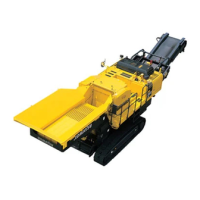
| Model | PC58UU-3 |
| Category | Construction Equipment |
| Language | English |







 Loading...