PC58UU-3 30-15
DISASSEMBLY AND ASSEMBLY
INSTALLATION OF ENGINE
AND WORK EQUIPMENT
PUMP ASSEMBLY
a The shapes of the water separator and fuel filter
of a machine, Serial No. 22001 or higher, are dif-
ferent from those of a machine of a lower Serial
No. The removal procedure for the engine and
work equipment pump assembly is the same,
however.
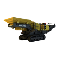
1. Use the two eyebolts on the engine and lift the
engine pump assembly (51). Bring the bolt of
the revolving frame mount (52) to the hole of the
engine-side bracket, lower the engine pump
assembly, attach the mounting bolt and nut to the
bracket and tighten the nut to the specified
torque.
3 Mounting nut: 59 – 74 Nm {6 – 7.5 kgm}
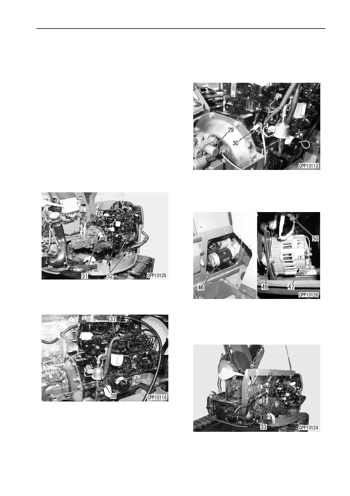
2. Connect the hose of the fuel pump (38) and the
fuel filter hose (37) to the engine pump assembly
and clamp the two hoses to the engine block.
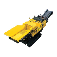
3. Connect the electrical harness and install each
connector and harness of the work equipment
pump solenoid (29), the engine speed sensor
(30), the fuel pump, etc. to the engine pump
assembly.
4. Connect each harness of the starting motor (40)
and alternator (47). Install the connector (50) of
the water temperature sensor (49) to the engine
and pump assembly.
5. Lift the canopy mounting frame (33) and set it in
position. Attach it with 4 bolts and tighten the
bolts to the specified torque.
4 Frame : 60 kg
(6)
ENGINE AND WORK EQUIPMENT PUMP ASSEMBLY
 Loading...