24185 Speaker wall/ceiling mount
- adjustable to any angle by special swivel joint assembly
SAFETY INSTRUCTIONS
INSTRUCTIONS
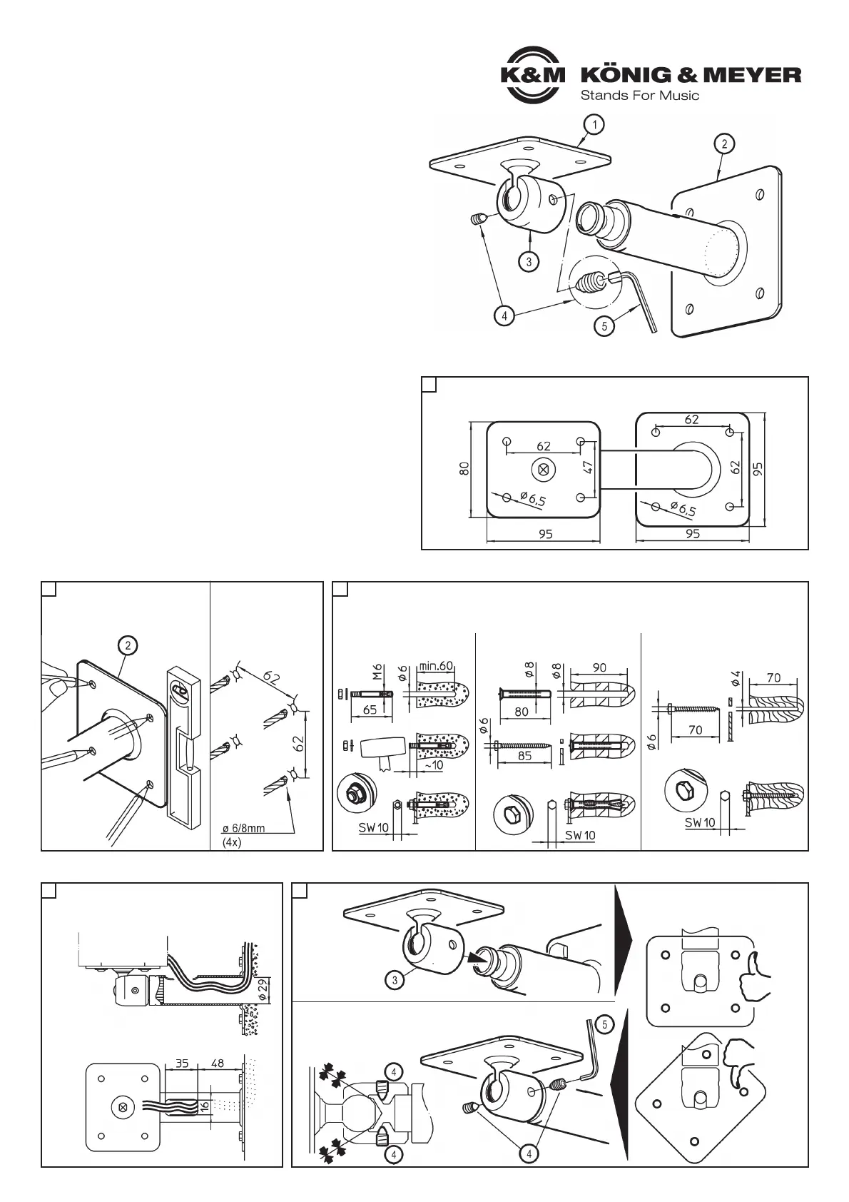
Are all listed parts in the delivery and in working order?
1 Loudspeaker plate
2 Wall plate with support tube
3 Joint
4 Pointed threaded pin M6 x 10 mm (2x)
5 Allen wrench SW3 for M6
ATTACH WALL PLATE TO THE WALL
HOLE PATTERNS
MOUNT THE LOUDSPEAKER MOUNT
A
D
- load bearing weight: max 10 kg
- not suitable for outdoors or moist rooms
- please refer to local mounting instructions
- (may possibly deviate from the examples provided in Section C)
- use 4 screws/anchors for the wall mount
- only use trained technicians to install the system
- only mount on suitable walls with the corresponding
- mounting materials (not included in the delivery)
- walls, that are too weak or have electrical and water conduits are not suitable.
- In case of doubt consult a qualified technician.
- Check the stability of the installation regularly.
- The universal ball joint is connected to the holding tube with two threaded
- pins 4 and may only be loosened when changing the position of the
- loudspeaker. In this process it is best to have two people hold the
- loudspeaker to ensure that it does not dislodge.
- Careful and attentive handling is required when adjusting the
- loudspeakers, due to the possibility of pinching or wedging of
- your hand.
- Check to ensure that the loudspeaker is suitable; particularly the
- threaded bushings.
NOTE for in-wall-cable-installation
- Wall plate opening (ø29 mm)
- Cable exit - 35 x 16 mm
a.
Place the joint 3
over the support
tube pivot bolts
d. The pressure asserted by the
d. threaded pins 4 between the
d. joint and socket holds the
d. loudspeaker in position
c. Tighten both threaded pins 4
c. with the Allen wrench 5.
b. Joint 3
b. Place the loudspeaker plate so
b. that the drill hole template can be
b. seen
speaker plate wall plate
E
1. Find a location on the wall
1. where you wish to mount the wall
1. plate, ensuring that it is vertical.
2. Mark the drill holes.
3. Drill the holes for the
3. wall plugs, 4x
3. -ø 6 for anchor bolts
3. -ø 8 for dowels
B C
concrete wall perforated bricks wood wall
2. a. For installation into stone or masonary walls, use an appropriate wall anchor (not supplied).
2. b. For installation on a wood or plaster wall, it is recommended that the wall adapter be attached
2. b. to a supporting wall stud, or other suitable support. The two Center holes in the wall plate can
2. b. be used for a stud wall installation.
 Loading...