Testing Continuity (Audible)
1. Connect the black test lead to the COM jack and the red
test lead to the V/Ω jack.
NOTE: The polarity of the red lead connection is positive (+).
2. Set the range switch in the position / . For model
GDT-295A it is necessary to push the / function
button to select between continuity or diode test mode.
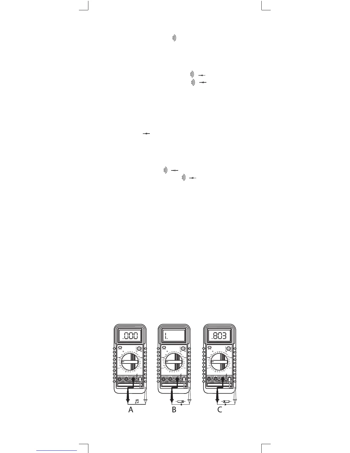
3. Connect the leads across the fuse or wire to be tested as
shown in diagram A.
4. If continuity exists (i.e., resistance < 50 Ω), a built-in buzzer
will sound.
Testing Diodes
1. Connect the black test lead to the COM jack and the red
test lead to the V/Ω/F jack. NOTE: The polarity of the red
lead connection is positive (+).
2. Set the range switch at / position. For model GDT-
295A it is necessary to push the / function button to
select between continuity or diode test mode.
3. Connect the leads across the diode as shown in diagrams
B & C. For a good silicon diode, the forward voltage drop
is about .6V. The reverse polarity will read as an open circuit
(OL).
21
 Loading...