Do you have a question about the Kopp GDT-293A and is the answer not in the manual?
Observe all normal safety rules concerning electrical current and meter misuse.
Follow all safety and operating instructions to ensure safe operation and good condition.
Explains symbols for important safety info, dangerous voltage, ground, insulation, AC/DC, diode, capacitor, transistor, frequency.
Disconnect power, inspect for faults, clean with damp cloth, ensure back cover is fastened.
Identifies power button, selector, LCD, input jacks, and sockets.
Details turning the meter on/off and the auto power-off feature for battery saving.
Guides connection of black/red leads to COM and other jacks based on selected function.
Steps for connecting leads and setting range for V--- and V~ measurements.
Steps for connecting leads in series and setting range for A--- and A~ measurements.
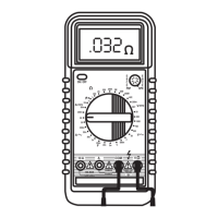
Connect leads across resistance, set Q range, and notes on high resistance readings.
Procedure to test continuity using the audible buzzer for resistance < 50 Ω.
Steps to test diodes, noting forward voltage drop and reverse polarity readings.
Procedure to test transistor hFE value using the dedicated socket.
Instructions for measuring capacitance on specific models using nF or µF positions.
How to measure temperature using a K-type thermocouple on model 293A.
Procedure for measuring frequency using the Hz function on model 295A.
Freezes the displayed reading and shows "D-H" symbol.
Adjusts voltage/resistance ranges on GDT-294A.
Selects DC or AC current measurement mode.
Silences the built-in buzzer for most functions.
Manually selects ranges or enables autoranging on GDT-295A.
Replace battery when low battery indicator appears; disconnect leads first.
Replace fuses with specified voltage and current ratings; disconnect leads first.
| Digits | 3.5 |
|---|---|
| Diode Test | Yes |
| Continuity Test | Yes |
| Battery | 9V |
| Category | Multimeter |
| Display | LCD |