Do you have a question about the Korg i2 and is the answer not in the manual?
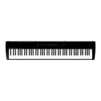
| Keyboard | 61 keys |
|---|---|
| Touch Response | Yes |
| Display | LCD |
| Built-in Speakers | Yes |
| Power Supply | AC adapter |
| MIDI | Yes |
| Outputs | L/Mono, R, Headphone |
| Connections | MIDI |
Details on voice and oscillator configuration for tone generation.
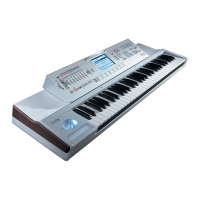
Information on key count, sensitivity, and model types.
Details on ROM capacity and sound/drum counts.
Specifications for ROM and RAM program storage.
Storage capacity for styles in ROM, RAM, and Card.
Number and type of multi-digital effects available.
Diagram illustrating screw points for i2 whole unit disassembly.
Diagram illustrating screw points for i3 whole unit disassembly.
Diagram showing screw locations for i2 lower case disassembly.
Diagram showing screw points for i2 panel assembly.
Diagram showing screw points for i2 keyboard assembly.
Diagram showing screw points for PU chassis disassembly.
Diagram showing screw points for LCD assembly.
Circuit diagram for the Main PCB (KLM-1631).
Circuit diagram for the Panel-LCD PCB (KLM-1625).
Circuit diagram for the Panel-L PCB (KLM-1624).
Circuit diagram for the Panel-R PCB (KLM-1626).
Component layout diagram for KLM-1625/1628 PCBs.
Component layout diagram for KLM-1626 PCB.
Component layout diagram for KLM-1631B PCB.
Component layout diagram for KLM-1624 PCB.
Diagram of equipment and settings required for diagnostic tests.
Procedure for entering the unit's internal test mode.
Tests the System ROM and Bus line integrity.
Tests write/read functionality of RAM cards.
Tests backup battery voltage and presence.
Checks panel switches and LEDs for proper operation.
Tests A/D converter, joystick, and rotary encoder.
Tests floppy disk drive functionality and disk integrity.
Checks TGL clock signal from IC14 to IC17 at 32MHz.
Checks TGL clock signal from IC17 to IC13 at 16MHz.
Checks CPU clock signal from IC32 to IC31 at 12.5MHz.
Checks TGL clock signal from IC17 to IC6 at 16.12MHz.
Checks reset signals from IC7 to IC8, IC31, IC23.
Checks crystal oscillator signal for CPU at 25.0MHz.
List of main ICs used in the device and their functions.
Pin assignment diagram for the UPD70433GD-5BB CPU.
Pin assignment diagram for the MBCS35104 TGL.
Pin assignment diagram for HD6433308B46F NKS.
Pin assignment diagram for HD63266F FDC.