Do you have a question about the Korg KRONOS 61 and is the answer not in the manual?
Instructions for accessing static test modes using switch combinations.
Explanation of navigation symbols and button functions within the test mode.
Visual inspection procedure for the unit's exterior, including case, knobs, and printing.
Steps for preparing the unit and checking LCD behavior, including USB and MIDI connections.
Procedure to test audio output by playing keys and checking for abnormalities.
Verifying LCD color output and rotary encoder response.
Confirming the displayed software version is the latest available.
Verifying the status of MIDI, Battery, USB, and Keybed components.
Confirming the implemented memory size displayed for KRONOS models.
Verifying the displayed number of keys and current date/time.
Checking fan speed control and RPM value behavior.
Verifying all LEDs turn on and have uniform brightness.
Confirming panel switches activate corresponding LEDs as per the table.
Verifying all LCD segments display white and checking for dust.
Verifying all LCD segments display black and checking for dust.
Checking the screen's display gradation from top to bottom for abnormalities.
Confirming that the LCD brightness changes periodically.
Procedure for calibrating the touch panel using stylus pen and specific screen prompts.
Verifying touch screen responsiveness and color changes when interacting with squares.
Confirming the buzzer sound is not too quiet during operation.
Testing ribbon controller movement (MAX, CENTER, MIN) and RAW value.
Verifying joystick movement (RIGHT, CENTER, LEFT) and smooth operation.
Testing joystick movement (UP, CENTER, DOWN) and smooth operation.
Verifying vector joystick movement (CENTER, RIGHT, LEFT, UP, DOWN) and smooth operation.
Testing rotary knobs and sliders for smooth operation and correct value display.
Testing rotary encoder rotation, value changes, and reset function.
Testing tempo knob rotation for CENTER, MAX, and MIN positions.
Testing EXP-2, DS-1H, and PS-2 pedals for MIN, CENTER, MAX, and FootSwitch functions.
Testing key touch sensitivity (medium, hard, soft) and checking for mechanical noise.
Verifying the selection of keyboard types (Normal, KDP1) on the LCD screen.
Testing after touch response for C4/C#4 keys and checking specific value ranges.
Selecting ErP capability (ON/OFF) based on serial number and instructions.
Procedure for loading the PSoC system after exchanging the main board or IC.
Instructions for assembling the left side panel, including screws and torque.
Instructions for assembling the right side panel, including screws and torque.
Assembly steps for the 61-key model's power unit, including screws and torque.
Assembly steps for the 73/88-key model's power unit, including screws and torque.
Assembly steps for the mother board specific to 73/88 key models.
Assembly steps for the mother board specific to 61 key models.
Steps for installing the Vector Joystick PCB, including orientation and screws.
Steps for installing the Encoder PCB, ensuring correct positioning and alignment.
Procedure for adding an LCD spacer to prevent contact between the LCD hood and touch panel.
Steps for installing the motherboard, mounting DIMM, and connecting harnesses.
Connecting and routing various harnesses (power, FAN, etc.) to the motherboard and panel.
Instructions for applying double-faced tape to shield seats and bending them for installation.
Steps for installing the motherboard, mounting DIMM, and connecting harnesses for 73/88 keys.
Routing harnesses and connecting power supply components for the instrument.
Instructions for pasting MB Shield and PWR Shield to the chassis of RH3.
Instructions for pasting MB Shield and PWR Shield to the chassis of RH3 for KRONOS-88.
| MIDI | In, Out, Thru |
|---|---|
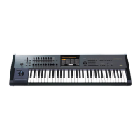
| Type | Workstation |
| Keyboard | 61-key, Semi-weighted |
| Sound Engines | 9 |
| Polyphony | Varies by engine, up to 200 voices |
| Effects | 12 Insert, 2 Master |
| Sequencer | 16-track MIDI |
| Sampling | Open Sampling System |
| Display | 8-inch color touchscreen |
| Storage | 62GB SSD, USB flash drive support |
| Controllers | Joystick, Ribbon controller |
| Audio Outputs | L/MONO, R, Individual 1-4 |
| USB | USB (A, B) |
| Connectivity | Ethernet |
| Weight | 14.3 kg |
| Power Supply | AC 100-240V, 50/60Hz |