Do you have a question about the Korg KRONOS 88 and is the answer not in the manual?
Overall system architecture diagram showing major components and connections.
Schematics for keyboard scanning circuitry for upper and lower keybeds.
Detailed circuit diagrams for the OMAP processing board (part 2).
Schematic for the front panel interface and controls.
Circuitry for connecting and driving the LCD display.
Schematic for the 88-key keyboard contact and scanning logic.
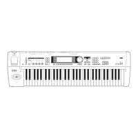
Check physical condition of case, knobs, paintings, and printings for damage.
Insert USB memory, connect MIDI, check LCD stability during Set List page display.
Calibrate the touch panel by touching specific points as instructed.
Verify touch input detection and color changes on screen squares.
Test key touch sensitivity from edge to edge, checking for errors or noise.
Test after-touch function for C4/C#4 keys and check value ranges.
| Set List Mode | Yes |
|---|---|
| MIDI | In, Out, Thru |
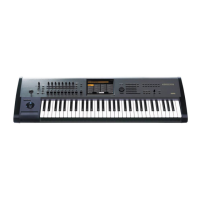
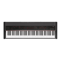
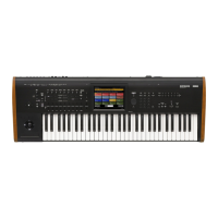
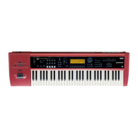
| Keyboard | 88-key RH3 (Real Weighted Hammer Action 3) |
| Sound Engines | 9 |
| Polyphony | Maximum 200 voices (varies by sound engine) |
| Display | 8" TouchView color TFT LCD |
| Sequencer | 16-track MIDI sequencer |
| Effects | 12 Insert FX, 2 Master FX, 2 Total FX |
| Weight | 24.1 kg |
| Sampling | Open Sampling System |
| KARMA | Yes |
| Outputs | L/MONO, R, Headphones |
| Inputs | Analog 1, 2 |
| External Storage | USB |
| Controllers | Joystick, Ribbon Controller |
| USB | USB-A (Ver. 2.0): 2x for external storage/MIDI controllers. USB-B (Ver. 2.0): 1x MIDI/Audio interface |
| User Sample Banks | 16 (128 MB total) |