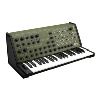
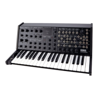
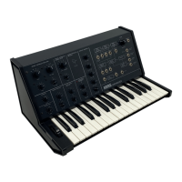
KORG MS-20
7. ADJUSTMENT PROCEDURE
7-1
Power
sup
ply check
1 .
Positive
lippte.
Should be no
more
than 2mVp-p,
Set oscilloscope vertical gain at lOmV/cm end
check
that
power
supply
ripple is
2mV or
less.
2.
Negative
ripple.
Same
as
positive,
should be
no
more
tharv
2mVp-pH
7-2.
Pitch adjustment
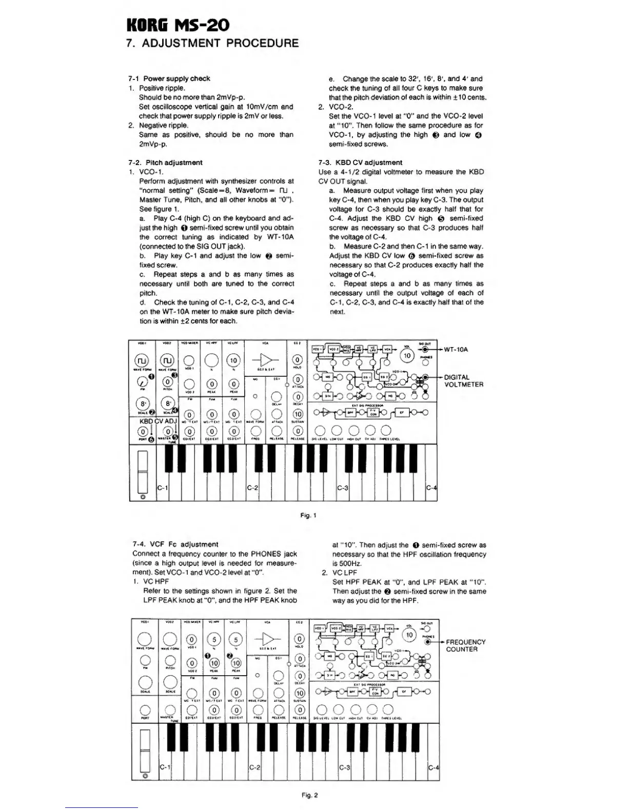
1, VCO-1.
Perform
adjustment
with synthesizer controls
at
"normal
setting”
(Scale
=8,
Waveform— fU
.
Master Tune. Pitch,
artd
all
other
knobs at
"0'%
See figure 1
.
a.
Play
C-4
(high
C) on
the keyboard and
ad-
just the high
O
sernl -fixed
screw
until
you
obtain
the correct
tuning
as
indicated
by WT-10A
(connected lolheSIG OUT
jack).
b.
Play key C-1 and adjust the low
^
semi’
fixed screw.
0
.
Repeat steps a and b as
many times
as
necessary until both
are
tuned
to the
correct
pitch.
d.
Check the
tuning
of
C*1, C-2,
G-3, and G-4
on
the
WT-10A meter to make sure pitch devia-
tion
is
within
±2
cents for each.
e. Change the
scale
to 32\ 1
6", 8',
and
4'
and
check
the
tuning
of
all four C keys to make
sure
that
the pitch
deviation of each Is
within
+
1 0 cents.
2.
VCO-2.
Set
the VCO-1
level
at and
the
VCO-2
level
at
'"10".
Then follow
the
same
procedure
as
for
VCO-1. by
adjusting
the
high
and
low
semt'fixed screws.
7-3.
KSDCV adjustment
Use a
4-1/2
digital voltmeter to
measure
the K6D
CVOUT signal.
a.
Measure
output
vottage
first when
you
play
key C-4, then when
you
play key C-3. The output
voltage for C-3 should be exactly halt that for
C-4. Adjust
the
KBD CV high
0
semi-tixed
screw
as
necessary
so
that
C-3
produces
half
the
vottage
of
C-4.
b.
Measure C-2
and
then C-1 in the same way.
Adjust the KBD CV low
0
semi-fixed screw as
necessary so that C-2 produces
exactly half ihe
voltage ot C-4.
c. Repeat steps a
and
b as
many times
as
necessary
until
the output
voltage of
each
of
C-1, C-2. C-3.
and
C-4 is exactly half that of the
next.
vHi
O®
rw
Kikl
&
o
®
6
KBOCVADJ
@1
o
irCO I
O
4
P
®
l
4
TtJT
®
C^t
O
®
P
4
U
®
®
%
®
H.M
®
K
TtlT
>
1^
Ul k
O
Uit
rpta,
o
fMjO
nrtP
o
o
«irj
4
r
O
C-2
®
®
iTT^
®
IfcJ
o^-
f>Bor^]o
fT^n
o-o
o
o o oo
imnirinT
C-3 C-4^
WT-10A
DIGITAL
VOLTMETER
Fig. 1
7-4.
VCF
Fc
adjustment
Ck>nnect
a
frequency
counter to the PHONES jack
(since a high
output
level
es
needed
tor
measure-
ment).
Set
VCO-1 and VCO-2
level
at
"0^
1.
VCHPF
Refer
to the settings shown in figure 2, Set the
LPF
PEAK knob
at
"0'\
and
the
HPF
PEAK knob
at
"10”.
Then
adjust the
O
semi-fixed screw as
necessary
so
that
the HPF oscillation
frequency
is 500Hz.
2.
VC LPF
Set
HPF
PEAK
at
’
0”.
and LPF PEAK at
”10",
Then
adjust
the
6
semi-fixed screw in the
same
way as you
did
for the
HPF.
FREQUENCY
COUNTER

 Loading...