EasyManua.ls Logo

Korg Nu:Tekt OD-S User Manual

Korg Nu:Tekt OD-S
16 pages
To Next Page IconTo Next Page
Page #1 background imageLoading...
Page #1 background image
- 1 -
EJ 1
2019
OD-S
NUTUBE OVERDRIVE KIT
Table of Contents
Main features ............................................................. 2
Cautions Before Assembly.......................................5
Tools to prepare ......................................................................5
Checking the parts .................................................................5
Assembly Parts List ................................................. 6
Assembly ...................................................................7
Adjusting and setting the main circuit board ...................9
Operation Check ........................................................ 9
Troubleshooting ......................................................................9
Part Names and Functions .................................... 10
Specifications .......................................................... 10
Recommended Settings........................................... 11
Normal OVERDRIVE .............................................................. 11
Tube OVERDRIVE ................................................................... 11
Hard Drive ................................................................................ 11
Mounting Diagram ....................................................13
List of mounted parts ............................................. 14
CIRCUIT DIAGRAM ................................................. 16
Question and Answer IconNeed help?

Do you have a question about the Korg Nu:Tekt OD-S and is the answer not in the manual?

Korg Nu:Tekt OD-S Specifications

General IconGeneral
Product colorBlack
Battery life (max)10 h
Number of notes-
Weight and Dimensions IconWeight and Dimensions
Depth96 mm
Width122 mm
Height55 mm

Summary

Main Features

About Nutube

Precautions

Location Precautions

Using the unit in certain locations can result in malfunction.

Power Supply Guidelines

Connect the designated AC adapter to an AC outlet of the correct voltage.

Handling and Care Instructions

Avoid breakage, do not apply excessive force. Wipe with a dry cloth.

Foreign Matter Prevention

Never set liquid containers near the equipment. Be careful not to let metal objects slip into it.

Cautions Before Assembly

Handling Parts Safely

Use caution to avoid injury from protruding parts. Use gloves and wash hands after working.

Screw Tightening Technique

Tighten screws perpendicularly. Avoid applying too much torque to prevent damage.

Tool Usage Safety

Be careful not to injure yourself or scratch surfaces when using tools.

Preventing Loss of Small Parts

Handle screws and nuts with caution to avoid losing them. Use included parts only.

Tools to Prepare

Required Tools

Needle-nose pliers, tweezers, screwdrivers, spanner/wrench are required.

Checking the Parts

Parts Verification

Ensure all parts are present before assembly. Contact for missing or damaged items.

Assembly Parts List

Assembly

Mount LED Holder and Main Circuit Board

Mount LED holder [8] and install main circuit board [20] onto the upper case [1].

Attach Jacks and Volume Control

Attach washers [18] for jacks, tighten nuts [17]. Attach washer [7] to volume control, tighten nut [6].

Mount Foot Switch and Circuit Board Cushion

Attach foot switch unit [13] and circuit board cushion [22] to Nutube circuit board [19].

Connect Circuit Boards

Connect Nutube circuit board [19] and main circuit board with harness A [21].

Mount Nutube Board and Battery Components

Mount Nutube circuit board unit [19] with cushion [22]. Attach battery cushion [12] and battery [11].

Final Assembly Steps

Connect foot switch harness. Adjust main circuit board. Close and secure lower case, attach rubber feet and knobs.

Adjusting and Setting the Main Circuit Board

Connect Power and Set Knobs

Connect battery/adapter. Turn TUBE GAIN to max, other knobs centered, EFFECT ON.

Adjust Trimmer Potentiometer

Turn fixed resistor to achieve maximum volume. Sound quality varies with bias voltage.

Set WIDE Switch

Turn WIDE switch ON for full-range booster. Turn OFF for a more cutting sound.

Operation Check

Troubleshooting Common Issues

Missing or Damaged Parts

Contact nutekt.org if parts are lost, missing, or damaged before assembly.

Assembly Errors

Contact nutekt.org if a part was broken during assembly.

Abnormal Sound Diagnosis

Check for loose screws or parts inside the unit if abnormal sound occurs.

Loose Controls and Jacks

Ensure nuts on volume controls and jacks are tightened securely.

Part Names and Functions

Volume and Tone Controls

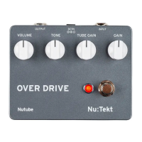
VOLUME knob adjusts overall volume. TONE knob adjusts sound sharpness/fullness.

Gain Controls and Switches

TUBE GAIN knob changes distortion waveform. GAIN knob adjusts distortion amount. EFFECT switch controls on/off.

Effect Indicator

The EFFECT ON/OFF LED indicates when the effector is active.

Specifications

Recommended Settings

Normal Overdrive Settings

Typical overdrive setting. Maximize TUBE GAIN for milder sound, use GAIN knob for distortion.

Tube Overdrive Settings

Full-range overdrive emphasizing tube sound. Turn WIDE switch ON and adjust GAIN.

Hard Drive Settings

Sound with hard distortion. If amp is distorted, lower GAIN knob.

Mounting Diagram

List of Mounted Parts

Circuit Diagram

Related product manuals