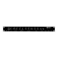
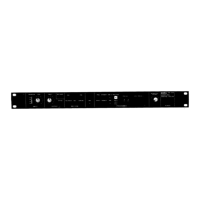
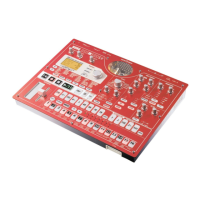
FEATURES AND FUNCTIONS
1. Front Pa
附
ilnputSection
ー
i,
Delay Time Section
11
Regeneration Section
寸「一一一一
Modulatior
。
。
HEADROOM LEVEL
A B
TIME(ms)
8
512
1024
FACTOR
xO.5
xO
忌耳れ
FEEDBACK
O
FILTER
O
2
1
。
。
INPU
DELAY TIME
①
Headroom
indicator
②
Input volume
③
Delay time range selector
④
Factor control
⑤
Feedbackcontrol
@
Filter control
⑦
Modulation intensity control
③
Modulation frequency control
• About Control Knobs
AII revolving pots feature dual concentric
stacked" knobs
The inner (front) knob controls Unit A
,
and the outer (back)
knob controls Unit 8
• Input Section
の
Headroom Indicator
This LEDmeter shows input levels. It shows the level of
the mixed signal composed of the input and feedback
signals.
②
Input Volume
Usedto adjust the input signal leve
l.
• Delay Time Section
③
Delay TimeRangeSelector
‑・・・・・
6
Usedto select delay time range for each uni
t.
Control of
delay timewithin the selected range is performed with
the Factor Control
④ .
1of 6ranges as shown below maybe selected.
Position of
Selector knob
1024
512
128
32
8
2
Delay Ti
町、
e
256ms ‑ 1024ms
128πlS ‑ 512ms
32ms ‑ 128ms
8ms ‑ 32ms
2ms ‑ 8πlS
O.5ms ‑ 2ms
fThis control revolves successivelY
,
l
Ihowever ranges change step‑by‑I
lstep as shown.
J
④
Factor Control
Usedto select delay time within range selected via Delay
Time Range Indicator
③
• Regeneration Section
⑤
Feedback Control
Used to control feedback level and phase. Whenexter‑
nal signals are input via the Feedback input on the rear
panel
,
the input level and phase are set via this contro
l.
(See page 8
,
Feedback Input
②.)
⑥
Filter Control
Used to controls the timbre of e
仔
ect sounds. Turning
the knob to the right brings on the high
‑c
ut filter cutting
high frequencies for a
warmer" sound
,
while turning it to
the left brings onthe low‑cut filter cutting low frequencies
for athinner
,
sharper sound
• Modulation Section
⑦
Modulation Intensity Control
Used to adjust the intensity of modulation.(Each Unit is
controlled independently
,
regardless of Modula tion Mode
Switch position.)
③
Modulation Frequency Control
Speed of delay time modulation is set via this contro
l.
(However
,
if the Modulation ModeSwitch
⑦
is set to IN
PHASEor OUTPHASE
,
then Unit A's control knob is us‑
edto control both Units' modulation frequency
,
with Unit
8's control having no e
行
ect on either Uni
t.)
⑨
Modulation Indicator
Flashes to indicate modulation speed and phase.