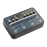
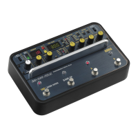
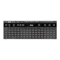
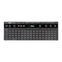
Section r‑Output Section
~
rSampling Section Ir
:~~~:'ll
Power Sectionl
NCY DIRECTA B EFFECT
au
ad
o
‑
8 2
9
,TION
OUTPUT SAMP
Ll NG
KII&勝。
。
。
。
⑪ Powerswitch
⑮ Powerindicator
⑮ Bypass indicator
⑪ Bypa鎚 switch
⑬ Sampling switch
⑫ Effect output volume
⑪ Direct output volume
⑩ Modulation modeswitch
⑨ Modulation indicator
⑩ Modulation ModeSwitch
This switch is used to select the relationship of modula‑
tion signals between Units Aand B. (Changes modula‑
tion added to Unit B.)
Oneof 3positions maybe selected as shown below.
Switch P
関 ition I Units A,Bmodulation
s
凹陥
T花E IMo帥 tiωO∞n of 伺 ch 川 i陪sc∞on川tro削111
ωt
剖副 Iy i川ndependen川tly.
IN PHASE
IModulation for both units is controlled by
using Unit A's LFO. LFO's are In Phase
OUTPHASE
IMo帥 tion for both units is controlled by
using Unit A'sLFO. LFO's are Out of
Phase.
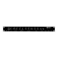
• Output Section
⑪ Direct Output Volume
Usedto adjust direct signallevel in
+Mix and,‑Mix out‑
puts.
⑫ E何ect Output Volume
Used to adjust effect signal levels in
+Mix and,‑Mix
outputs.
• Sampling Section
⑬ Sampling Switch
Each unit maybeused as asampling unit by setting this
switch to either RECor PLAY.(See page9
, Using Units
as Sampling Machines" for information onrecording and
playback.)
This should beset to OFFfor normal use as adelay unit
•
~ypass
Section
⑪ Bypass Switch
Both units use this single bypass switch .Note that when
the footswitch is connected to the back panel
,and only
one unit is set to BypassOn
,Bypass will beset 0行when
the bypass switch is pressed.
Whense! to Bypass On
,it becomesimpossible to output
E
付ect sounds from the rear panel +Mix,‑Mix and Ef‑
fect outputs. Direct sounds maybe output
⑮ Bypass Indicator
Li ghts when bypass is set to ON
• Power Section
⑮ PowerIndicator
Li ghts when power is turned ON
⑪ PowerSwitch
7・・・・・・