31
KraftPowercon Sweden AB, Hjalmar Petris väg 49, S-352 46 Växjö, Sweden, Tel: +46 470-705200, Fax: +46 470-705201,
www.kraftpowercon.com
If you select the fifth option, “External blocking”, an additional function will be added. The input
then serves as a remote controlled shut-down function for the rectifier units. Open input means
that the rectifier units are shut down, i.e. put in a condition with the DC output shut off, and with
the alarm text displayed on screen. A closed input results in normal operation.
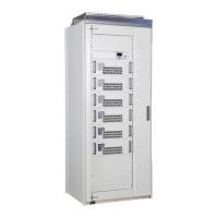
5.13.11 Special functions
Certain customised special functions are also built into the standard model.
You can use the XM1 and XM2 parameters to activate these functions. For
use of these functions, see separate description.
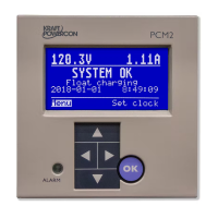
5.13.12 Other functions
Satellite panel
There is the option of connecting another operator panel, for monitoring in
a control room, for example. This unit is called a satellite panel. The
satellite panel is exclusively a slave unit for the actual operator panel.
As all display information is continually copied from the actual operator
panel via a series channel to the satellite panel, the satellite panel may be perceived as slightly
“slow”. Depending on the amount of traffic in the series channel, there may be a delay of up to a
few seconds before you get a response from the display when you press the button. Where there is
a need of settings and other more advanced use it is therefore recommended that you mainly use
the actual operator panel.
Set the value Yes if a satellite panel is installed.
I/O unit 2
As an option, an additional I/O unit can be connected in order to extend the number of alarm
relays from the usual four to a total number of eight relays.
Set the value Yes if a second I/O unit is installed.
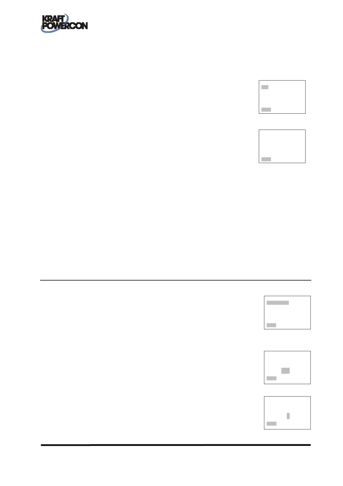
5.14 SYSTEM DATA
5.14.1 General
Under System data there are a number of basic parameters that in principle
describe the rectifier and design of the installation. These are therefore
normally not changed following the installation being taken into service.
If PCM2 is used solely as a monitor (number of rectifiers = 0) the Rated voltage and System
belonging options cannot be selected.
5.14.2 Specify rated voltage
The rated voltage must agree with the system's nominal voltage and with the
rated voltage that is found in the equipment's rated plate.
5.14.3 Specify rated current
The specified rated current must agree with the rated current that is present
on the rectifier's rated plate. This refers to the total rated current of the
rectifier, i.e. the sum of the rated currents of all the rectifier modules.
==ADV./SYSTEM DATA=
Rated voltage: 220V
Rated current: 10A
No.of rectifiers: 1
System belonging: -
________________________________
Select Return
Adjust
rated voltage
110V
________________________________
Ready
Adjust
rated current
010A
________________________________
Ready
===././SPECIALFUNCT.=
XM1 No
XM2 No
________________________________
Select Return
=./FUNCTIONS/OTHERS
Satellite panel No
I/O unit 2 No
________________________________
Select Return
 Loading...