PT-571HDCP, PT-572HDCP+ Quick Start
PT-571HDCP, PT-572HDCP+ Quick Start Guide
This guide helps you install and use your PT-571HDCP, PT-572HDCP+ for the first time.
Go to www.kramerav.com/downloads/PT-571HDCP to download the latest user manual and check if
firmware upgrades are available.
Step 1: Check what’s in the box
PT-571HDCP, PT-572HDCP+ DVI Line Tx/Rx
2 Mounting brackets per unit
1 Power supply (12V DC) per unit
We highly recommend using only Kramer UNIKAT cables with these products. If using 3
rd
party shielded CAT-6A cables, both ends of the
shield must be soldered to the connectors for the products to function properly. Do not use any jumpers, unshielded wall plates or mid-
span cable connections. These extenders are not compatible with HDBaseT technologies. Prior to signal extension, ensure that the
extension line cable is lying straight and not coiled.
Step 2: Get to know your PT-571HDCP, PT-572HDCP+
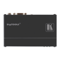
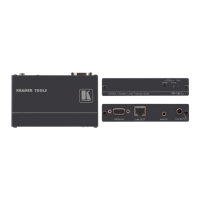
PT-571HDCP DVI Line Transmitter
Connect to the DVI source
+12V DC connector for powering the unit
Connect to the IN RJ-45 connector on the PT-572HDCP+
Lights only when the machine is powered (whether directly from the power adapter or via the
PT-572HDCP+) and an input is connected.
If no input is connected the unit invokes the power save mode automatically turning off the
power.
The terms HDMI, HDMI High-Definition Multimedia Interface, and the HDMI Logo are trademarks or registered trademarks of HDMI Licensing Administrator, Inc.
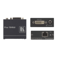
PT-572HDCP+ DVI Line Receiver
Connect to the OUT RJ-45 connector on the PT-571HDCP
Lights red when receiving power only, orange when output and power are attached, and yellow
when both an active input and output are attached.
Connect to the DVI acceptor
+12V DC connector for powering the unit