Adjust the cable compensation equalization level
Insert a screwdriver into the small hole and carefully
rotate it, to trim the appropriate level
Adjust the output signal level
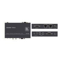
UXGA OUT 1 15-pin HD Connector
Connect to the first UXGA acceptor
UXGA OUT 2 15-pin HD Connector
Connect to the second UXGA acceptor
Illuminates when receiving power
Connect to the LINE IN connector on an additional
TP-202
Using a UTP CAT 5 cable with RJ-45 connectors at
both ends (the PINOUT is defined in 4.1)
Connect to the LINE OUT RJ-45 connector on the
transmitter
For example, the PT-110, as Figure 3 illustrates
+12V DC connector for powering the unit
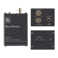
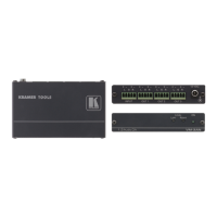
Figure 2 defines the TP-202 underside panel:
Figure 2: TP-202 (Underside Panel)
Slide the switch to NORMAL to retain the polarity
Slide the switch to INVERT to invert the VS polarity
By default, both switches are set to NORMAL
Slide the switch to NORMAL to retain the polarity
Slide the switch to INVERT to invert the HS polarity
By default, both switches are set to NORMAL