4 Your TP-205A
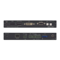
Figure 1 and Table 1 define the TP-205A:
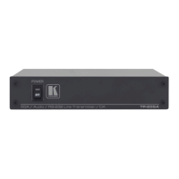
Figure 1: TP-205A
Table 1: TP-205A Features
# Feature Function
1 POWER Switch Illuminated switch for turning the unit ON or OFF
2 IN Connect to the computer graphics source
3
XGA 15-pin HD
Connector
LOOP Connect to a display or to the XGA IN connector of an additional
TP-205A unit
4 LINE OUTPUTS RJ-45
Connectors
Connect to
1
the LINE IN RJ-45 connector on a receiver
2
(from 1 to 5)
5 IN Connects to the unbalanced stereo analog audio source
6
ANALOG AUDIO
3.5mm Mini Jack
LOOP Connect to an unbalanced stereo analog audio acceptor or to the
ANALOG AUDIO IN connector of an additional TP-205A unit
7 S/PDIF – ANALOG SELECT
Selector Button
3
Release to select digital audio (S/PDIF)
Press to select analog audio
8 LOOP Connect to a digital audio acceptor or to the S/PDIF IN connector of an
additional TP-205A unit
9
S/PDIF RCA
Connector
IN Connect to the digital audio source
10 IN Connect the two connectors on the left (GND and IN) to a PC or
remote controller (see section 5.4)
11
RS-232 Terminal
Block Connector
LOOP Connect the two connectors on the right (GND and LOOP) to the GND
and IN connectors of an additional TP-205A
12 12V DC +12V DC connector for powering the unit
1 Using a UTP CAT 5 cable with RJ-45 connectors at both ends (the PINOUT is defined in Table 3 and Figure 5)
2 For example, the Kramer TP-124, the Kramer TP-46, and so on
3 RS-232 can be embedded only when the S/PDIF ANALOG Selector Button is set to the analog state