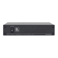
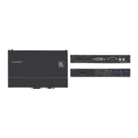
5 Configuring the TP-205A
This section describes how to:
Connect the TP-205A (see section 5.1)
Connect an additional TP-205A (see section 5.2)
Wire the CAT 5 LINE IN / LINE OUT RJ-45 Connectors (see section 5.3)
Control via RS-232 (see section 5.4)
5.1 Connecting the TP-205A
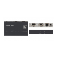
You can connect the TP-205A to up to five receivers. Use it to transmit the video,
audio and RS-232 control signals via CAT 5 UTP cable.
To connect the TP-205A as illustrated in the example in Figure 3, do the
following:
1. Connect an XGA source (for example, a laptop’s graphics card) to the XGA IN
15-PIN HD connector and an audio source to the ANALOG AUDIO IN 3.5mm
mini jack
1
, for example, using a Kramer C-GMA/GMA cable (VGA HD15M
+Audio jack to VGA HD15M +Audio jack)
2
.
2. Press the SELECT button to select the ANALOG input
3
.
3. Connect an RS-232 cable with a 9-pin D-sub connector at one end to the laptop,
and the other end to the 2 left-hand pins of the terminal block connector
4
(GND
and IN) on the TP-205A RS-232 port
5
.
4. Connect the LINE OUTPUT CAT 5 connectors as follows
6
:
The LINE OUT 1 RJ-45 connector on the TP-205A to the LINE IN
RJ-45 connector on the TP-124
7
via UTP cabling
8
(with a range of
more than 300ft (>100m))
9
The LINE OUT 5 RJ-45 connector on the TP-205A to the LINE IN
RJ-45 connector on the TP-124
7
, via UTP cabling
8
(with a range of
more than 300ft (>100m))
1 Or alternatively to the digital audio S/PDIF IN RCA connector
2 Not supplied. The full list of Kramer cables is on our Web site at http://www.kramerelectronics.com. Alternatively, you can
connect an XGA source to the XGA IN 15-pin HD connector, and a separate audio source to the AUDIO IN 3.5mm mini jack
3 If the digital audio input is selected, release the SELECT button
4 The two right pins (GND and LOOP) can be connected to the GND and IN connectors on an additional TP-205A unit
5 As defined in Figure 6 and Table 4 (see section 5.4)
6 You do not have to connect all the outputs
7 Refer to the separate user manual, which can be downloaded from the Internet at http://www.kramerelectronics.com
8 For details of how to wire a CAT 5 LINE IN / LINE OUT RJ-45 connector, see section 5.3
9 The TP-46 is connected to an additional TP-46 unit for transmitting the signal further