VM-218DTxr, VM-218DT – Defining VM-218DTxr HDMI/HDBT Switcher DA
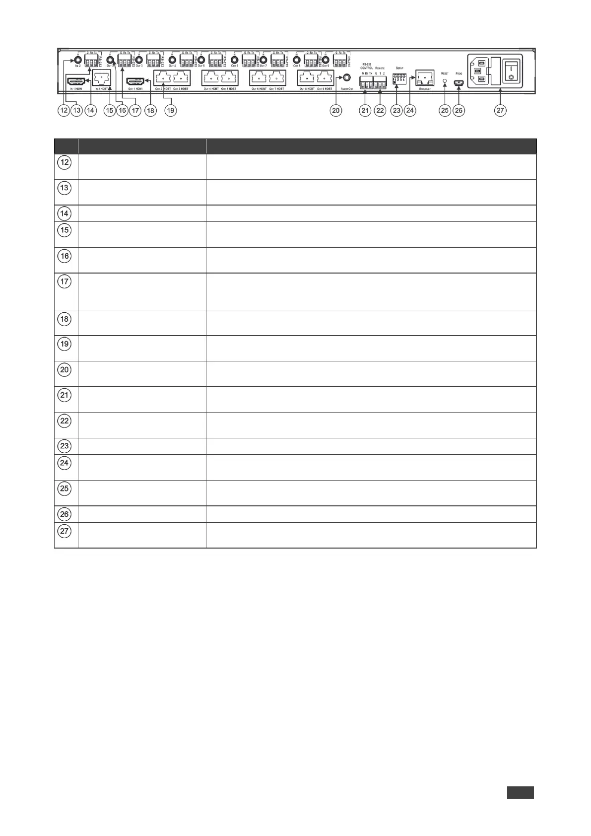
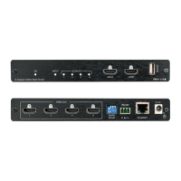
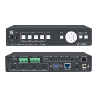
Figure 2: VM-218DTxr HDMI/HDBT Switcher DA Rear Panel
IN 2 IR on a 3.5 Mini Jack
Connect to an IR emitter/sensor cable for IR link extension via IN 2
HDBT.
IN 2 RS-232 (G, Rx, Tx)
Terminal Block Connector
Connect to a serial controller for RS-232 link extension via IN 2 HDBT.
Connect to an HDMI source.
IN 2 HDBT on RJ-45
Connectors
Connect to an HDBT transmitter (for example: TP-780Txr for
VM-218DTxr and TP-580T for VM-218DT).
IR on 3.5 Mini Jacks (for
OUT 2 to 9)
Connect to remote IR emitter/sensor cables to IR control the devices that
are connected to the HDBT acceptors.
RS-232 OUT (G, Rx, Tx)
Terminal Block Connectors
(2 to 9)
Connect to serially control the devices connected to the HDBT acceptors.
Connect to the HDMI input of an additional DA or connect to a local
monitor.
OUT HDBT RJ-45
Connectors (2 to 9)
Connect to HDBT receivers (for example: TP-780Rxr for VM-218DTxr
and TP-580R for VM-218DT).
AUDIO OUT 3.5mm Mini
Jack
Connect to an analog audio acceptor.
RS-232 CONTROL 3-pin
Terminal Block
Connect to the serial controller to control the VM-218DTxr.
REMOTE 3-pin Terminal
Block
Use to set the device behavior.
Connect to LAN for Ethernet extension via IN and OUT HDBT ports and
remote IP control of the VM-218DTxr.
Press and hold while powering on the device to reset to factory default
parameters.
Connect to a PC to perform firmware upgrades.
Mains Power Connector,
Fuse and Switch
Connect to the mains supply.