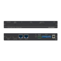
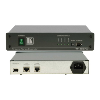
VM‑4HDT, VM‑3HDT, VM‑2HDT – Operating the VM‑4HDT, VM‑3HDT and VM‑2HDT
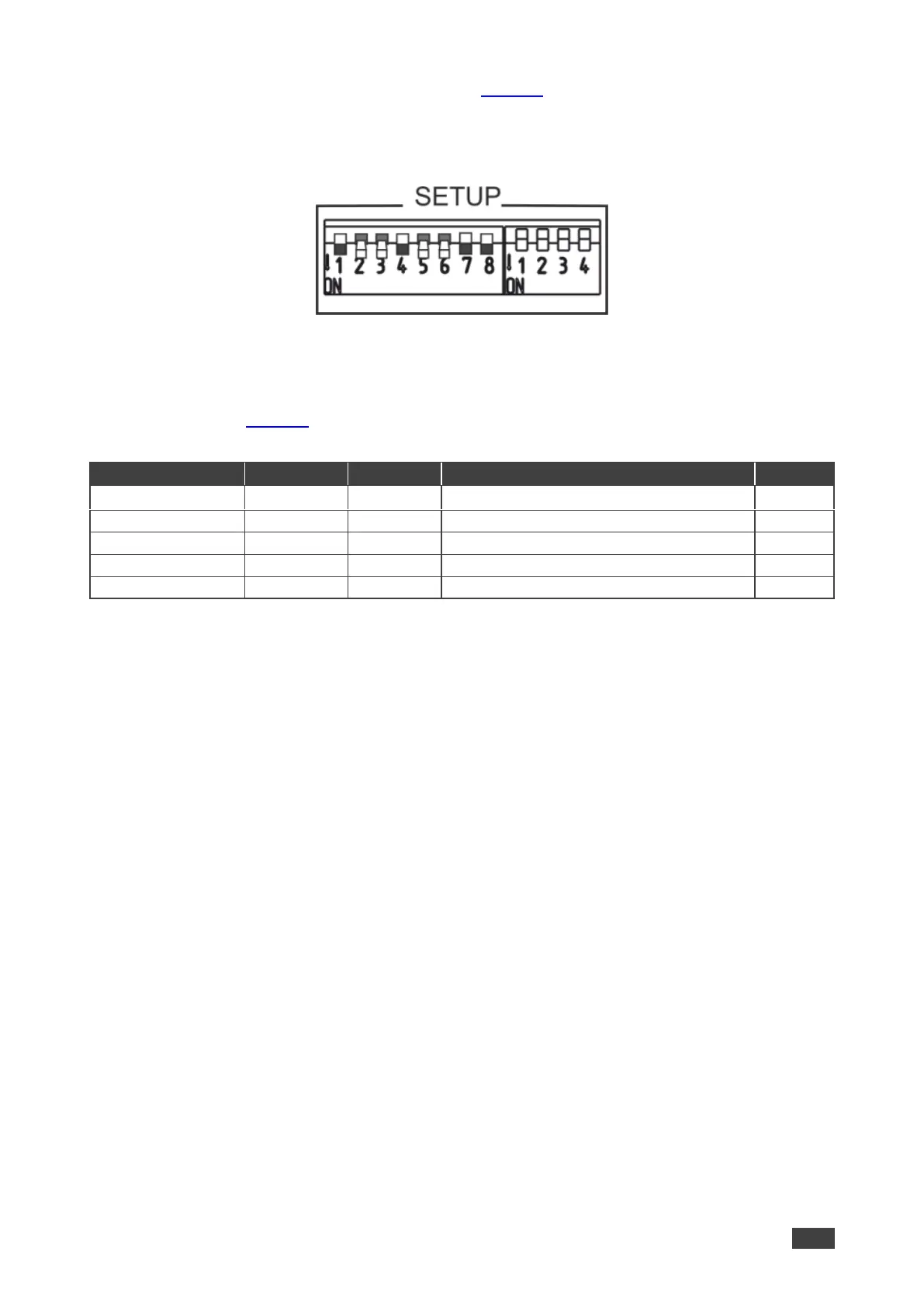
For example, in the DIP-switch setup shown in Figure 8, DIPs 1, 4, 7 and 8 are set to OFF.
This means that IR signals can be transferred through channels 1 and 4 and RS-232
commands can be passed via channels 3 and 4. All the other channels are set to ON and
therefore their related IR and RS-232 communication is disabled.
Figure 8: VM‑4HDT DIP-Switches Setup
Signal Routing
The example in Figure 9 shows the VM‑4HDT connected to four TP-580R devices. The table
below summarizes the types of connections:
IR signal Routing
To route the IR signal you have to use the Kramer external IR sensor on one end and the
Kramer IR emitter cable on the other end.
In this example, an IR emitter is connected to the streamer and IR sensors are connected to
each TP-580R device. This setup lets you remotely control the streamer via any of the
receiver devices using the streamer’s IR remote control transmitter.
RS-232 Signal Routing
A laptop or a Kramer Control device (for example, the SL-240C controller) can be used to
send RS-232 control commands over HDBaseT to the remote connected device.
In this example, a laptop is connected to the RS-232 terminal block connector on the
VM‑4HDT and the RS-232 ports on TP-580R (3) and TP-580R (4) are connected to the
projector. With this type of setup, you can control the projectors via the laptop.
RS-232 commands are sent to both projectors:
• When identical (for example, both are Projector A models), both respond to these
commands.
• When different (for example, Projector A and Projector B models), the Projector A
commands affect only Projector A and are ignored by Projector B.