VP-427X1 Quick Start Guide
This guide helps you install and use your VP-427X1 for the first time.
Go to www.kramerav.com/downloads/VP-427X1 to download the latest user manual and check if firmware
upgrades are available.
Step 1: Check what’s in the box
VP-427X1 4K HDBT/HDMI Receiver/Scaler
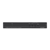
Step 2: Get to know your VP-427X1
Lights green when device is powered by power supply or PoE (PD).
Press to select the input (HDBT or HDMI).
Lights blue when the HDBT input is selected.
Lights blue when the HDMI input is selected.
Connect to an IR sensor to control a remote device connected to the transmitter side
via HDBT tunneling.
Connect to an external IR emitter to control a local device from the transmitter side.
Press to enter/exit the on-screen display (OSD) menu. Press together with the –
button to reset the output to 1080p resolution.
In OSD, press to choose the highlighted menu item. Press together with the
FREEZE/+ button to reset the output to XGA resolution (1024x768).
In OSD, press to move back through menus or decrement parameter values. Press
together with the MENU button to reset the output to 1080p resolution.
In OSD, press to move forward through menus or increment parameter values. When
not in OSD, press to freeze the display.
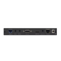
Connect to a PC via a LAN to setup and monitor the VP-427X1 via the Windows
software, as well as upgrade the firmware.
Connect to a USB stick to perform firmware upgrades.
HDBT RJ-45 Connector with
PoE (PD)
Connect to a transmitter (for example, the Kramer TP-789Txr).
Connect to an HDMI source.
RS-232 CONTROL 3-pin Terminal Block
Connector
Connect to a serial controller or PC.
REMOTE Contact-Closure 4-pin
Terminal Block Connector
Connect to contact closure switches, an occupancy sensor and/or toggle switches
(contact between the desired pin and GND pin), to turn display on or off (see Step 6:
Operate VP-427X1).
AUDIO 5-pin Terminal Block Connector
Connect to a balanced stereo audio acceptor.
Connect to an HDMI acceptor.
Connect to the supplied power adapter.
The terms HDMI, HDMI High-Definition Multimedia Interface, and the HDMI Logo are trademarks or registered trademarks of HDMI Licensing Administrator, Inc.
Step 3: Mount VP-427X1