Install VP-427X1 using one of the following methods:
• Attach the rubber feet and place the unit on a flat surface.
• Fasten a bracket (included) on each side of the unit and attach it to
a flat surface (see www.kramerav.com/downloads/VP-427X1).
• Mount the unit in a rack using the recommended rack adapter
(see www.kramerav.com/product/VP-427X1).
• Ensure that the environment (e.g.,
maximum ambient temperature & air
flow) is compatible for the device.
• Avoid uneven mechanical loading.
• Appropriate consideration of equipment
nameplate ratings should be used for
avoiding overloading of the circuits.
• Reliable earthing of rack-mounted equipment should be maintained.
• Maximum mounting height for the device is 2 meters.
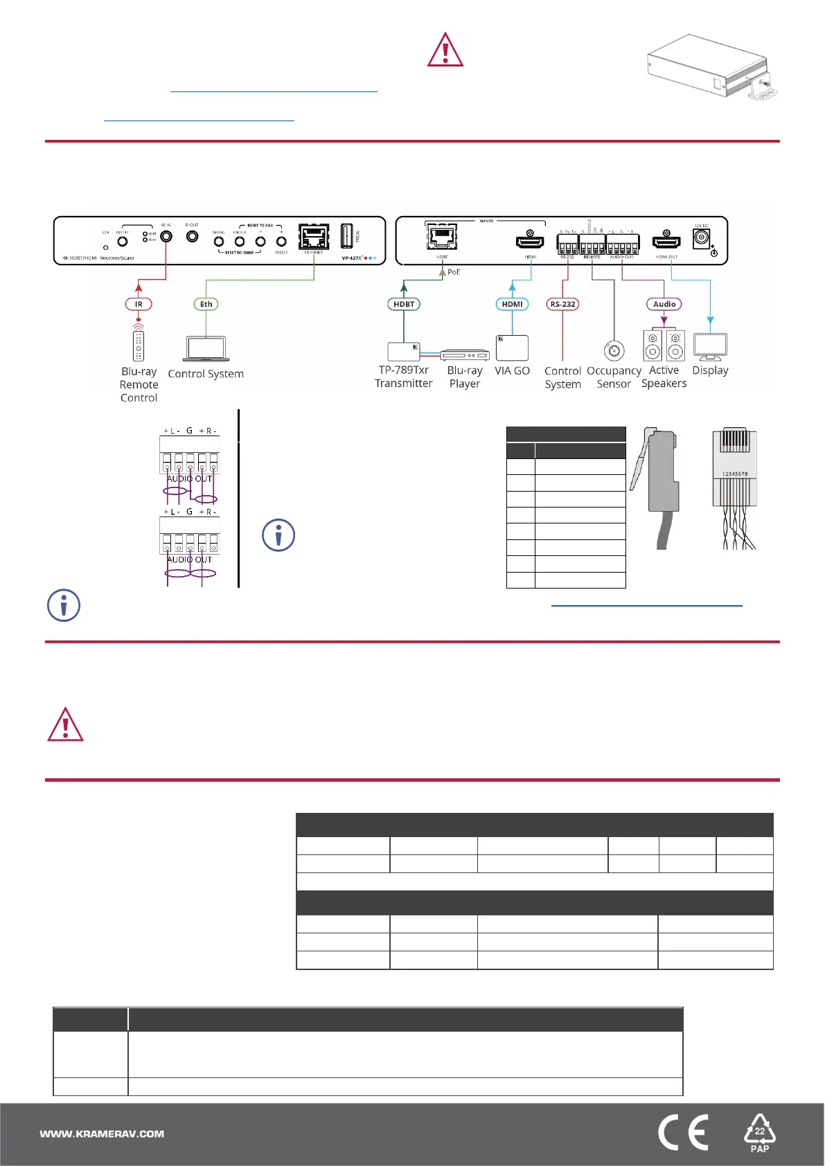
Step 4: Connect inputs and outputs
Always switch OFF the power on each device before connecting it to your VP-427X1.
Connecting the audio output
Wiring the RJ-45 Connectors
To a balanced
stereo audio
acceptor:
This section defines the TP pinout, using
a straight pin-to-pin cable with RJ-45
connectors.
To an unbalanced
stereo audio
acceptor:
For HDBT cables, it is recommended
that the cable ground shielding be
connected/soldered to the connector
shield.
To achieve specified extension distances, use the recommended Kramer cables available at www.kramerav.com/product/VP-427X1.Using
third-party cables may cause damage!
Step 5: Connect power
If there is no PoE input, connect the power adapter to the VP-427X1 and plug it to the mains electricity.
Safety Instructions (See www.kramerav.com for updated safety information)
Caution:
• For products with relay terminals and GPI\O ports, please refer to the permitted rating for an external connection, located next to the terminal or in the User Manual.
• There are no operator serviceable parts inside the unit.
Warning:
• Use only the power cord that is supplied with the unit.
• Disconnect the power and unplug the unit from the wall before installing.
To operate VP-427X1, use one of these
options:
• Front panel buttons.
• Remotely, by RS-232 serial commands
transmitted by a touch screen system, PC,
or other serial controller
• Embedded web pages via the Ethernet.
RS-232 Control / Protocol 3000
Example: (Route video HDBT INPUT to HDMI OUTPUT): #ROUTE1,1,1<CR>
Default Ethernet Parameters
Default Username/password:
Operating via the remote control switches
Momentarily connect the desired pin to the GND pin to select an input:
One button toggles between display on and display off (instead of using two separate buttons for
on and off). Alternatively, using the VP-427X1 OSD, configure turning the display on or off
according to whether a switch is open or closed, for example, when using an occupancy sensor.

 Loading...