INSTALLATION DIAGRAM
B
A
Z1
Z2
Z2
1m
1m
2
3
4
5
8
B
6
6
77
1B
1A
1m
Z2
1B
1m
1A
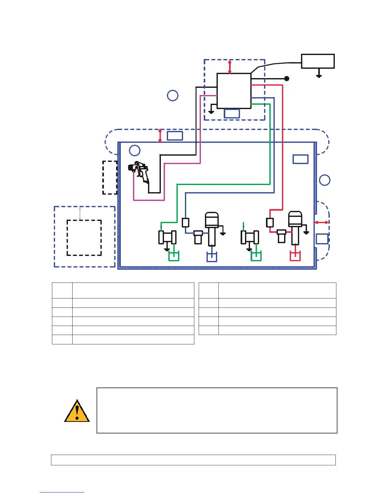
A Explosive area : area 1 (Z1) or area 2 (Z2)
(spray booth)
4BASEpump
B Non explosive area (safe area) 5 SOLVENT pump (base)
1A CYCLOMIX
TM
MICRO control bay 6 Filter
1B CYCLOMIX
TM
MICRO fluid module 7 Fluid pressure regulator
2CATApump 8Gun
3 SOLVENT pump (cata)
Nota : To connect the SOLVENT pump (CATA) to the CYCLOMIX MICRO machine :
- choose a machine set up with 1 catalyst and one cata solvent,
- or disconnect the CATA hose at non-return valve level (CATA) of the machine and replace it connecting
the SOLVENT hose (CATA).
The 1 m distance indicated in the diagram is given for your information only and
KREM LIN REXSON shall not be liable for it. T he user is liable for the exact
delimitation of the zones which depends on the materials used, the material
environment and the use conditions (refer to EN 60079 -10 standard).
The 1 m distance can be adapted if the analysis the user carries out calls for it.