Do you have a question about the KROHNE 4000 Series and is the answer not in the manual?
Information is important to the installation/operation of the meter.
Risk of damage to the meter or installation.
Instruction MUST be observed in order to comply with Hazardous Areas Certification.
Risk of electric shock.
Non specific hazard that could result in injury.
Risk of burning.
Risk of injury.
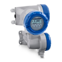
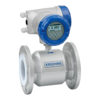
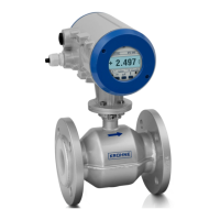
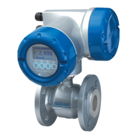
Describes OPTIMASS/OPTIGAS flowmeter systems, sensors, and converters.
Details the MFC 300F and MFC 300F T6 mass flow converters.
Covers OPTIMASS 1000, 1010C, and 1300C mass flow meters and sensors.
Details OPTIMASS 1000 T6, 1010C T6, and 1300C T6 models.
Information on OPTIMASS 2000, 2010C, and 2300C flow meters.
Covers OPTIMASS 3000, 3010C, and 3300C flow meters.
Details OPTIMASS 4000, 4010C, OPTIGAS 4000, and 4010C.
Information on OPTIGAS 5000, 5010C, and 5300C.
Covers OPTIMASS 7000, 7010C, and 7300C flow meters.
Details OPTIMASS 8000k, 8010kC, and 8300kC models.
Information on OPTIMASS 8000, 8010C, 8300C, 9000, 9010C.
Information on device data plates and their contents.
General conditions for temperature limits of flowmeters.
Temperature limits for MFC 300F and MFC 300F T6 converters.
Temperature limits for OPTIMASS 1000, 1010C, 1300C.
Temperature limits for OPTIMASS 1000 T6, 1010C T6, 1300C T6.
Temperature limits for OPTIMASS 2000, 2010C, 2300C.
Temperature limits for OPTIMASS 3000, 3010C, 3300C, 7000, 7010C, 7300C.
Temperature limits for OPTIMASS 4000, 4010C, OPTIGAS 4000, 4010C.
Temperature limits for OPTIMASS 8000k, 8010kC, 8300kC.
Temperature limits for OPTIMASS 8000, 8010C, 8300C.
Temperature limits for OPTIMASS 9000 and 9010C.
Temperature limits for OPTIGAS 5000, 5010C, 5300C.
Discusses painted finishes and their temperature limitations.
General guidelines for connecting separated systems.
Specifies parameters for connecting cables in separated systems.
Requirements for equipotential bonding in installations.
Illustrates terminal connections for sensors and converters.
General information on electrical connections for the devices.
Details non-intrinsically safe signal input/output connections.
Details intrinsically safe signal input/output connections.
Discusses maintenance-free properties and periodic checks.
Step-by-step guide for replacing the mains fuse.
Procedures and requirements for returning devices for service.
| Type | Electromagnetic Flowmeter |
|---|---|
| Measurement Principle | Electromagnetic induction |
| Accuracy | ±0.2% of measured value ±1 mm/s |
| Process connection | Flange |
| Material | Stainless steel, PTFE |
| Process Temperature Range | -40°C to +180°C (depending on liner material) |
| Operating pressure | Up to 40 bar (depending on size and material) |
| Process Pressure Range | Up to 40 bar (depending on size and material) |
| Approvals | ATEX, IECEx, FM, CSA |
| Output | 4-20 mA, Pulse, Frequency, HART, PROFIBUS PA |
| Protection Class | IP68 (depending on model) |
| Power Supply | 24 V DC, 100-240 V AC, 20-36 V DC (depending on model) |