Do you have a question about the KROHNE MFC 400 and is the answer not in the manual?
Documents the electronic revision status and its impact on compatibility.
Specifies the allowed applications and parameters for the mass flowmeters.
Lists directives the device conforms to and the presence of the CE mark.
Covers copyright, disclaimer, product liability, warranty, and documentation information.
Provides essential safety guidelines for personnel operating the device.
Details the items included in the product package and checks to perform upon receipt.
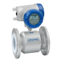
Describes the two available versions: compact and remote.
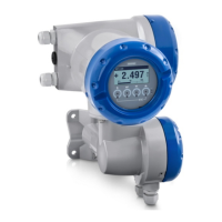
Illustrates and labels the components of the field housing.
Explains the information found on the device's nameplate.
Shows an example nameplate detailing electrical connection data for inputs and outputs.
General precautions and considerations for installing the device.
Lists precautions for reliable installation, such as space and environmental conditions.
Instructions and cautions for mounting the compact version of the device.
Details on mounting the field housing for the remote version.
Step-by-step guide for mounting the field housing onto a pipe.
Instructions for mounting the field housing onto a wall, including spacing for multiple units.
Crucial safety warnings related to electrical connections, including power disconnection and hazardous areas.
Specifies requirements for standard and hazardous area signal cables.
Details the process of connecting signal cables to the field housing and connection box.
Explains the importance and methods of grounding the flow sensor.
Instructions for connecting power to different housing variants, including voltage and grounding.
Provides an overview of available input/output combinations and modular options.
Details fixed I/O configurations for Ex i, Profibus PA, and Foundation Fieldbus.
General description of available inputs and outputs.
Details the operation modes, specifications, and features of the current output.
Explains the functionality, modes, and scaling of pulse and frequency outputs.
Describes the active, passive, and NAMUR modes for status outputs and limit switches.
Details the active, passive, and NAMUR modes for control inputs.
Details current output and pulse/frequency output specifications for Ex i applications.
Explains HART® connection for active and passive modes.
Steps to follow before connecting power and switching it on.
Describes the initial self-test and operation after power-on.
Identifies and explains the device's display and physical operating keys.
Outlines the hierarchical structure of the device's menu system.
Describes functions available for HART® connection, including Quick Setup.
Details functions within the "Quick Setup" menu for language, reset, and configuration.
Explains the functions available under the "Test" menu, including status and actual values.
Covers setup functions for process input, density, concentration, and diagnostics.
Details calibration procedures for zero and density.
Step-by-step guide for performing automatic and manual zero calibration.
Instructions for on-site density calibration using one or two points.
Describes measurement functions like flow and density.
Explains flow direction, process noise damping, and low flow cutoff.
Details the different density modes (Process, Fixed, Referred, Standard).
Covers I/O configuration settings for damping and suppressing small flow rates.
Describes current output modes, spans, and alarm settings.
Covers settings for optical keys and display backlight.
Details functions for loading, saving, and resetting device configurations.
Explains the access authentication concept and levels for protecting configuration.
Outlines simulation functions for testing device installation and configuration.
Explains how the device performs diagnostics and displays status messages per NAMUR NE 107.
Details status groups and their associated status signals (Failure, Function Check, etc.).
Step-by-step instructions for replacing the signal converter's electronic components.
Discusses typical inductance and resistance values for identifying driver or sensor coil faults.
General information and cautions regarding returning devices for service.
Instructions for proper disposal of the device in accordance with legislation.
Briefly describes the Coriolis measuring principle and refers to sensor-specific documentation.
Provides general technical data and points to additional resources.
Details the physical dimensions and weight of the device.
Describes materials used for the signal converter housing and flow sensor.
Details general electrical connection standards, power supply, and cable specifications.
General information about inputs/outputs, abbreviations, and current output settings.
Details resolution, uncertainty, temperature coefficient, and settings for current outputs.
Describes HART® protocol, version, load requirements, and device drivers.
Details output data, function, pulse rate/frequency, and settings for pulse/frequency outputs.
Covers adjustable features and operating data for status outputs and limit switches.
Details operating data for control inputs in modular I/Os and Ex i versions.
Technical specifications for PROFIBUS DP, including profile, function blocks, and output data.
Technical specifications for PROFIBUS PA, including current consumption and function blocks.
Technical specifications for FOUNDATION Fieldbus, including function blocks and output data.
Details Modbus RTU specifications, address range, and supported function codes.
Lists CE, Non-Ex, Functional Safety, Hazardous Areas (ATEX, NEPSI, FM/CSA, IECEx), and Custody Transfer approvals.
Introduces the HART® protocol and its application in the signal converter.
Lists electronic and HART® software revisions over time.
Explains supported connection variants for HART® communication (point-to-point, multi-drop).
Illustrates the point-to-point connection setup for HART® communication.
Maps HART® dynamic variables to device variables for various I/O configurations.
| Brand | KROHNE |
|---|---|
| Model | MFC 400 |
| Category | Measuring Instruments |
| Language | English |